
The transition from a vague idea to a concrete engineering specification is one of the most critical phases in systems engineering. Historically, this phase relied heavily on textual documents, spreadsheets, and static diagrams. While functional, these methods often struggled to capture the complexity and interdependencies inherent in modern system architectures. This is where the Systems Modeling Language (SysML) proves its value. By leveraging a standardized modeling language, teams can construct a living representation of their system before physical prototyping begins. This guide explores how to utilize SysML to structure early system concepts effectively.
Why SysML Matters for Conceptualization 🧠
Early system concepts are often ambiguous. Stakeholders might describe a desired function, but the technical implementation remains unclear. Textual requirements can be contradictory or open to interpretation. A model offers a single source of truth that is both visual and logical. SysML was designed to address these challenges within the context of Model-Based Systems Engineering (MBSE).
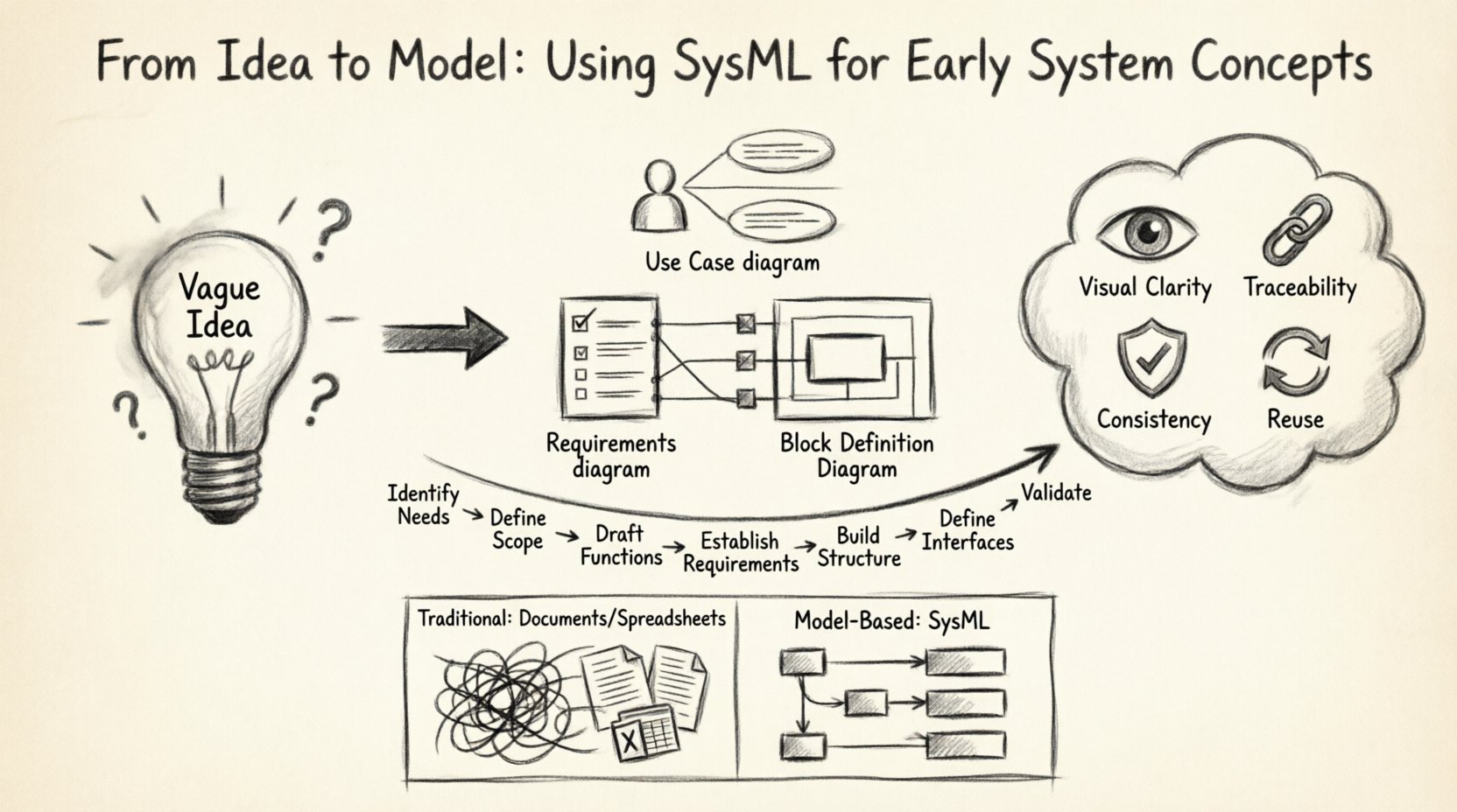
Adopting SysML for early concepts provides several distinct advantages:
- Visual Clarity: Complex relationships become easier to understand when mapped visually rather than described in paragraphs.
- Traceability: Links between requirements, functions, and structural components can be established immediately.
- Consistency: The language enforces strict rules, reducing the likelihood of logical errors in the design.
- Reuse: Standardized elements allow for the reuse of patterns across different projects or system families.
When moving from concept to model, the goal is not to create a perfect simulation immediately. Instead, the objective is to define boundaries, interfaces, and capabilities. This reduces risk early in the lifecycle, where the cost of change is lowest.
Understanding the SysML Core Diagrams 📐
SysML provides a suite of diagram types, each serving a specific purpose. For early system concepts, three diagram types are particularly vital. They allow engineers to capture what the system must do, what it needs to satisfy, and what it is made of.
1. Use Case Diagrams 🎯
Use Case diagrams describe the functional behavior of a system from the perspective of external actors. In the early stages, this helps define the scope of the system. It answers the question: “Who interacts with this system and what do they need it to do?”
Key elements include:
- Actors: Represent users, other systems, or external environments.
- Use Cases: Specific goals or functions the system performs.
- Relationships: Associations, generalizations, and dependencies between actors and use cases.
By mapping these relationships early, teams ensure that all stakeholder needs are accounted for before structural design begins. It prevents the common error of building features that no one actually uses.
2. Requirements Diagrams 📋
Requirements diagrams are the backbone of traceability. They allow engineers to define system requirements and link them to other model elements. Unlike a document list, a model requirement is an object that can be referenced, analyzed, and validated.
Common relationships in this diagram include:
- Satisfy: Links a requirement to a specific element that fulfills it.
- DeriveRequre: Indicates that a requirement was derived from another requirement.
- Refine: Adds detail to a high-level requirement.
- Verify: Links a requirement to a test or verification method.
During the concept phase, requirements are often high-level. A model allows these to be decomposed logically. For example, a high-level safety requirement can be linked to specific subsystems that manage safety functions.
3. Block Definition Diagrams (BDD) 🧱
Blocks represent the physical or logical components of a system. BDDs define the structure and hierarchy. In early concepts, this is not about detailed engineering drawings but about defining the major subsystems and their interfaces.
Key concepts in BDDs include:
- Parts: Instances of blocks within a composite block.
- References: Connections to blocks outside the current context.
- Interfaces: Defined points of interaction between blocks.
- Value Properties: Quantities such as mass, power, or cost associated with a block.
This diagram type moves the conversation from “what it does” to “what it is.” It sets the stage for defining internal interactions.
The Modeling Workflow: Step by Step 🔄
Creating a SysML model is a disciplined process. It requires moving from abstract needs to concrete structures. The following workflow outlines a standard approach for translating ideas into models.
- Identify Stakeholders and Needs: Start by listing who the users are and what problems they face. This feeds directly into Use Case diagrams.
- Define System Scope: Determine the boundary of the system. What is included and what is external? This clarifies the context for all subsequent diagrams.
- Draft Functional Flow: Outline the primary functions using Use Cases. Ensure no critical function is missed.
- Establish Requirements: Write down the constraints and goals. Assign unique identifiers to each requirement for traceability.
- Construct Structural Hierarchy: Create the Block Definition Diagram. Break the system into major subsystems.
- Define Interfaces: Specify how subsystems communicate. This is critical for hardware/software partitioning.
- Review and Validate: Check for consistency between requirements, functions, and structure. Ensure all requirements are satisfied by the defined structure.
This iterative process ensures that the model evolves as understanding deepens. It is not a linear path but a cycle of refinement.
Connecting Requirements to Structure 🔗
One of the most powerful aspects of SysML is the ability to connect requirements to structural elements. This linkage ensures that every part of the system has a purpose derived from a need. Without this connection, engineering efforts can drift, leading to feature creep or missed requirements.
Consider a scenario where a requirement states that the system must operate in extreme temperatures. In a traditional document, this might sit on a page with no clear link to the hardware. In a SysML model, you can link this requirement to a specific thermal management block. If the requirement changes, the impact on the thermal block is immediately visible.
Benefits of this traceability include:
- Impact Analysis: Quickly see what changes when a requirement is modified.
- Gaps Identification: Spot requirements that have no corresponding structural element.
- Redundancy Elimination: Identify structures that do not satisfy any current requirement.
Avoiding Common Pitfalls ⚠️
While SysML offers significant benefits, misapplication can lead to confusion. Teams new to the language often make specific mistakes during the conceptual phase.
- Over-Modeling: Trying to model every detail too early. Early concepts should focus on major boundaries and interfaces, not internal logic.
- Inconsistent Terminology: Using different names for the same concept across diagrams. This breaks traceability.
- Neglecting Interfaces: Focusing too much on internal blocks and ignoring how they interact with external systems.
- Ignoring Requirements: Creating structural models without linking them back to the original needs.
Adhering to a disciplined modeling standard helps mitigate these risks. Documentation of modeling conventions should be part of the project setup.
Comparison: Traditional vs. Model-Based Approaches
To better understand the shift in methodology, consider the following comparison between traditional document-based engineering and model-based approaches.
| Feature | Traditional Document-Based | Model-Based (SysML) |
|---|---|---|
| Traceability | Manual cross-referencing in Word/Excel | Automated links within the model |
| Consistency | Prone to human error and version drift | Enforced by language semantics |
| Visualization | Static, disconnected diagrams | Dynamic, connected views |
| Change Management | Difficult to assess impact | Clear impact analysis via dependencies |
| Communication | Text-heavy, requires interpretation | Visual, standardized notation |
Collaboration and Communication 🤝
Models serve as a communication bridge between different engineering disciplines. Mechanical, electrical, and software engineers often speak different languages. SysML provides a common vocabulary.
When a mechanical engineer defines a structural block, the software engineer can see the interfaces and data flows associated with that block. This reduces the friction of handoffs. It allows for parallel work streams where teams can develop their subsystems simultaneously, relying on the stable interfaces defined in the model.
Key aspects of collaboration include:
- Shared Repository: All stakeholders access the same model data.
- Viewpoints: Different users can see different slices of the model relevant to their role.
- Validation: Teams can review the model together to catch errors before implementation.
This shared understanding minimizes the risk of integration issues later in the lifecycle. It shifts the conversation from “I thought you meant this” to “The model shows this connection.”
Internal Block Diagrams and Interaction 📡
While Block Definition Diagrams show the hierarchy, Internal Block Diagrams (IBD) show the connections. In early concepts, IBDs help define how data, power, or signals flow between components.
When defining these connections:
- Define Ports: Specify where a block connects to the outside world.
- Define Flows: Specify the type of data or material moving through the connection.
- Define Constraints: Set limits on the flow, such as bandwidth or pressure.
This level of detail is crucial for verifying that the conceptual design is physically feasible. It helps identify bottlenecks or interface mismatches early.
Extending the Model with Constraints ⏱️
SysML supports constraints through parametric diagrams. While often associated with detailed analysis, they can be used in early concepts to define performance goals.
For example, if a system must accelerate within a certain time, a constraint can be defined on the relevant blocks. This links physical properties (mass, force) to performance requirements. It ensures that the structural decisions made during the concept phase align with the performance goals.
This approach prevents the scenario where a structure is designed that cannot meet the performance metrics. It forces engineers to consider the physics of the system early on.
Managing Evolution and Change 📈
Systems rarely stay static. Requirements change, technologies evolve, and constraints shift. A model-based approach handles change better than static documents because the relationships are explicit.
When a requirement changes:
- Update the requirement node in the model.
- Review all satisfied elements.
- Identify which blocks or functions need modification.
- Update the affected diagrams.
This process is systematic. It ensures that no downstream impact is missed. The model acts as a map of the system’s dependencies, guiding the change management process.
Integration with Other Standards 🌐
SysML is designed to work within a broader ecosystem of standards. It can integrate with other modeling languages or standards as needed. For instance, it can interface with standards for data exchange or specific industry regulations.
This interoperability is vital for large-scale systems where multiple teams and organizations collaborate. It ensures that the model remains a valuable asset throughout the entire product lifecycle, from concept to retirement.
Final Thoughts on Implementation 💡
Implementing SysML for early system concepts requires a shift in mindset. It moves the focus from documenting the system to defining the system. This distinction is subtle but profound. A document describes what has been decided. A model defines what the system is.
Success depends on discipline and clarity. Teams must agree on the level of detail required for the concept phase. They must prioritize traceability over complexity. And they must treat the model as a living artifact that evolves with the project.
By following these guidelines, organizations can build a robust foundation for their engineering efforts. The initial investment in modeling pays dividends through reduced rework, clearer communication, and higher quality systems. The path from idea to model is a journey of clarity. With SysML, that journey becomes structured, traceable, and reliable.
The future of systems engineering lies in this structured approach. As systems become more complex, the need for a rigorous modeling language will only grow. Starting early with these practices sets the stage for success in the later stages of design and development.

