Software systems grow in complexity over time. As requirements evolve, the interactions between components must remain clear, maintainable, and capable of supporting increased load. The Unified Modeling Language (UML) Sequence Diagram stands as one of the most effective tools for visualizing these dynamic behaviors. However, a basic sequence diagram only shows a happy path. To truly design for scalability, engineers must understand how to model alternative flows, asynchronous events, and complex state transitions without creating visual noise.
This guide explores advanced techniques for constructing sequence diagrams that serve as reliable documentation for scalable systems. We move beyond simple request-response models to address real-world scenarios where latency, failure, and concurrency are the norm. By applying these patterns, you ensure that your architectural documentation reflects the robustness of the underlying implementation.
🛠 Understanding Scalability in Modeling
Scalability in software architecture refers to the ability of a system to handle growing amounts of work or its potential to be enlarged to accommodate that growth. In the context of modeling, scalability means the diagram itself must remain readable as the number of interactions increases. A diagram that works for a single user flow often becomes a tangled web when scaled to thousands of concurrent requests.
Why Basic Diagrams Fail at Scale
When teams attempt to capture every edge case in a single sequence diagram, the result is often a “wall of text” that no developer can parse effectively. This leads to several issues:
- Cognitive Overload: Readers cannot distinguish critical paths from optional behaviors.
- Maintenance Burden: Updating a monolithic diagram for a small change becomes error-prone.
- Loss of Context: High-level architectural decisions get buried in low-level interaction details.
To avoid these pitfalls, scalable modeling requires abstraction. We must group interactions logically and use specific notations to denote variability. This approach allows the diagram to remain stable even as the underlying code changes frequently.
🔗 Core Components Revisited for Complex Systems
Before diving into advanced patterns, we must ensure the foundational elements of the sequence diagram are utilized correctly. While many practitioners use these components intuitively, precise usage is critical for clarity.
- Lifelines: Represent participants in the interaction. For scalability, group related lifelines under a single frame to indicate a subsystem boundary.
- Activation Bars: Show when an object is actively performing an action. Overcrowding these bars makes it hard to see concurrency. Use staggered activations to indicate parallel processing.
- Messages: Distinguish clearly between synchronous (blocking) and asynchronous (non-blocking) calls. This distinction is vital for understanding system bottlenecks.
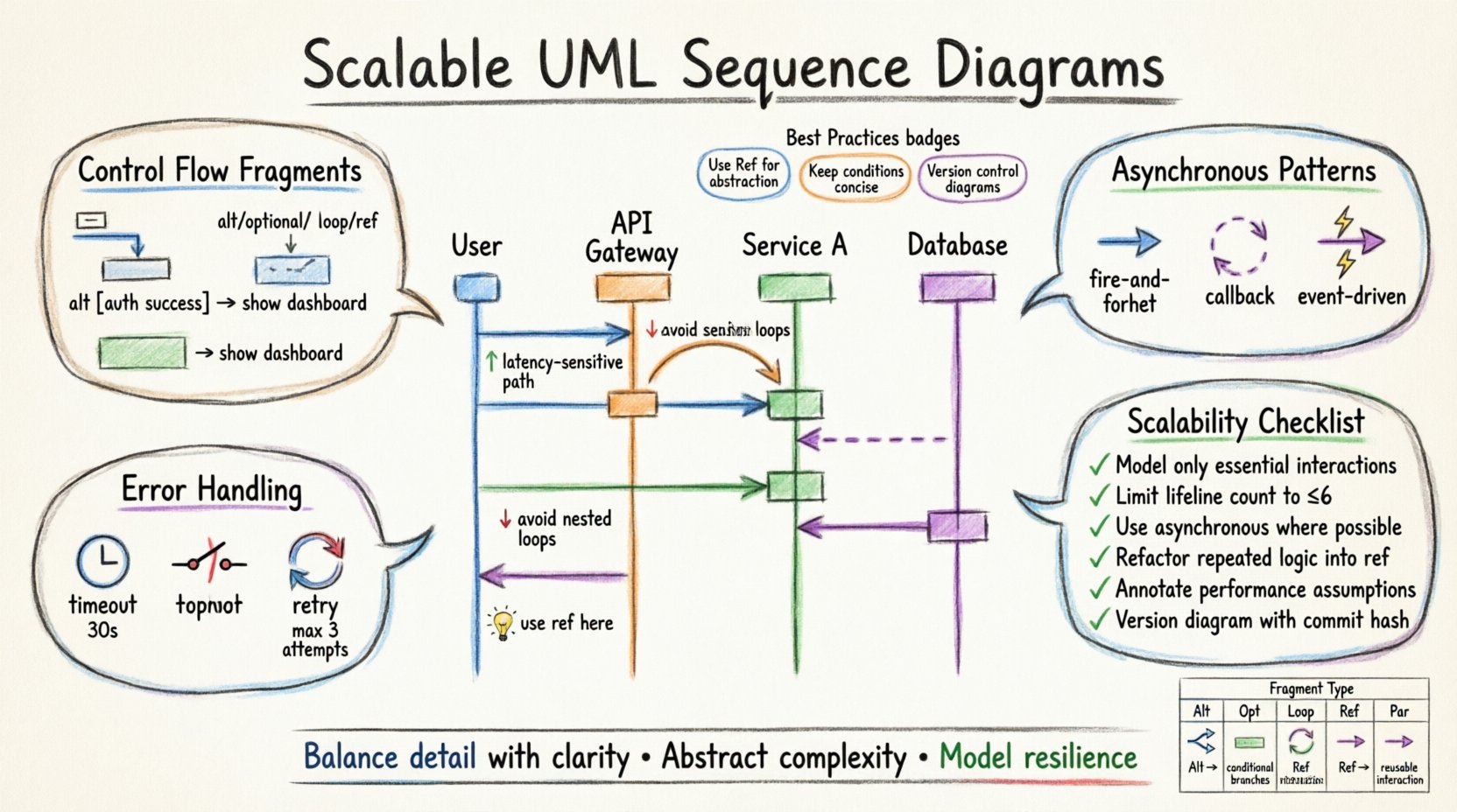
🧩 Mastering Control Flow Fragments
Control flow fragments are the building blocks of conditional logic within a sequence diagram. They allow you to encapsulate specific scenarios without cluttering the main flow. Using these correctly is the primary method for managing complexity.
1. The Alt Fragment (Alternative)
The alt operator is used when multiple mutually exclusive paths exist. It is essential for modeling decisions where the outcome depends on a specific condition. For example, a payment gateway might route a transaction to a credit card processor or a bank transfer service based on the currency.
Best practices for alt fragments:
- Keep the condition text concise and placed in the top-left corner of the fragment.
- Ensure that every possible logical outcome is represented, even if it is an error state.
- Avoid nesting too many alt fragments, as this creates a “spaghetti” visual effect.
2. The Opt Fragment (Optional)
Use the opt operator when a sequence of messages is optional. This is common in scenarios where a feature might be disabled or a notification might be skipped due to user settings. Unlike alt, opt implies that the main flow continues regardless of whether the optional block is executed.
3. The Loop Fragment
The loop operator represents iterative behavior. It is frequently used to model batch processing or polling mechanisms. A loop should be annotated with a condition, such as “while queue is not empty”.
When modeling loops for scalability:
- Indicate the scope clearly. Does the loop happen within a single thread or across a distributed system?
- Consider adding a “break” condition to show how the loop terminates to prevent infinite processing scenarios.
- Do not draw every iteration. Use the loop notation to imply repetition, keeping the diagram height manageable.
🔄 Managing Asynchronous Complexity
In modern distributed systems, synchronous calls are often a bottleneck. Scalable architectures rely heavily on asynchronous messaging. In sequence diagrams, this is represented by open arrowheads rather than solid filled arrows.
Why Asynchronous Matters
When a sender does not wait for a response, the system can handle more concurrent requests. This is critical for high-load environments. Modeling this correctly helps developers understand where threading or message queues are required.
Patterns for Asynchronous Flows
- Fire-and-Forget: A message is sent without an expectation of a return value. Use this for logging or telemetry data.
- Callback Mechanisms: The initial request triggers a process, and a subsequent message returns the result. This must be explicitly drawn to show the decoupling of the request and response.
- Event-Driven Triggers: Use dotted lines or specific notations to show that an event in one subsystem triggers an action in another without a direct call.
🧱 Abstraction Strategies: Ref and Include
As diagrams grow, readability becomes the primary constraint. Two powerful mechanisms help manage this: ref and include. These allow you to hide complexity by referencing other diagrams or common patterns.
The Ref Fragment (Reference)
The ref operator allows you to replace a sequence of messages with a reference to another diagram. This is ideal for breaking down large systems into manageable sub-flows. For instance, a complex authentication process can be collapsed into a single ref box that points to a detailed authentication sequence diagram.
Benefits of using ref:
- Modularity: Teams can work on different sub-diagrams independently.
- Focus: High-level architects see the flow without getting bogged down in details.
- Maintainability: Changes to the detailed flow do not require redrawing the main diagram.
The Include Fragment
The include operator denotes that the content of one fragment is always part of another. It is similar to a function call in programming. Use this for standard procedures that occur in multiple places, such as “Validate Input” or “Log Transaction”.
Caution should be taken to ensure that the included fragment is generic enough to be reused without modification. If the logic varies slightly, use an alt fragment instead.
⚠️ Error Handling and Timeouts
Scalable systems must be resilient. A diagram that only shows success cases is misleading. You must explicitly model how the system behaves when things go wrong.
Timeouts
In distributed systems, network latency is unpredictable. If a service does not respond within a specific timeframe, the caller must proceed to a fallback or error state. Represent this by adding a “timeout” constraint on the activation bar or using a specific message label.
Failure Propagation
- Immediate Failure: The error is caught and handled locally.
- Cascading Failure: One service fails, causing dependent services to fail. Modeling this helps identify single points of failure.
- Circuit Breakers: Use specific notation or notes to indicate that a service stops accepting requests after a threshold of failures is reached.
Retry Logic
Transient errors are common. Diagrams should indicate if a message is retried. You can use a loop fragment labeled “Retry on Failure” with a limit, such as “max 3 attempts”. This informs the reader that the system has built-in resilience.
📊 Interaction Patterns Comparison
To assist in selecting the right notation for your specific scenario, refer to the table below. This comparison highlights the intent and usage of common fragments.
| Fragment Type | Intent | When to Use | Scalability Impact |
|---|---|---|---|
| Alt | Alternative Paths | Branching logic based on conditions | High. Keeps logic separate and clear. |
| Opt | Optional Behavior | Features that may be disabled | Medium. Reduces visual noise for optional features. |
| Loop | Iteration | Batch processing or polling | High. Prevents drawing repetitive steps. |
| Ref | Abstraction | Complex sub-processes | Very High. Enables modular documentation. |
| Par | Parallelism | Concurrent operations | High. Clarifies thread safety and race conditions. |
🛡 Best Practices for Diagram Maintenance
A sequence diagram is only useful if it remains accurate. As the codebase evolves, diagrams can become outdated quickly. To maintain scalability in your documentation:
- Version Control: Store diagrams in the same repository as the source code. This ensures they are updated alongside the features they describe.
- Review Cycles: Include diagram updates in the code review process. If the interaction changes, the diagram must change.
- Consistency: Use a standard naming convention for messages and participants. Consistency reduces the cognitive load for readers.
- Abstraction Levels: Maintain multiple versions of the diagram. One for high-level architecture (coarse-grained) and one for implementation details (fine-grained).
🚧 Common Pitfalls to Avoid
Even experienced modelers make mistakes. Being aware of common traps helps you produce cleaner, more scalable diagrams.
- Over-Modeling: Do not model every single method call. Focus on the business logic and system boundaries. Detail belongs in the code, not the diagram.
- Inconsistent Notation: Mixing different styles of arrows or lifelines confuses the reader. Stick to the standard UML 2.0 syntax.
- Ignoring State: Sequence diagrams often imply state changes without showing them. If state is critical to the flow, use an Object Lifeline with state transitions or annotate the messages.
- Vertical Spacing: Do not spread messages too far apart vertically. It creates unnecessary scrolling and breaks the flow of reading.
✅ Scalability Review Checklist
Before finalizing a sequence diagram for a production system, run it through this checklist. This ensures the diagram supports the architectural goals of the project.
| Check | Question | Pass Criteria |
|---|---|---|
| 1 | Are all edge cases covered? | Error states and timeouts are visible. |
| 2 | Is the flow readable? | No overlapping lines or confusing crossings. |
| 3 | Is abstraction used? | Complex sections are referenced via ref. |
| 4 | Are lifelines consistent? | Participants are named clearly and consistently. |
| 5 | Is concurrency clear? | Parallel blocks are marked with par. |
| 6 | Is it up-to-date? | Matches the current codebase behavior. |
🌐 Integrating with Architecture Documentation
Sequence diagrams should not exist in isolation. They are part of a broader documentation ecosystem. To maximize their value:
- Link to Class Diagrams: Reference the classes involved in the sequence diagram to provide static context.
- Link to Component Diagrams: Show where the participants reside within the system topology.
- Link to API Specifications: If the interactions are external, link to the API documentation for detailed payload structures.
This interconnected approach ensures that a developer can trace the flow from high-level architecture down to specific implementation details without losing context.
🔍 Analyzing Performance Through Diagrams
While sequence diagrams are primarily for logic, they can also hint at performance characteristics. By analyzing the depth and breadth of interactions, you can identify potential bottlenecks.
- Depth of Calls: A long chain of synchronous calls indicates a high latency risk. Each step adds network or processing overhead.
- Branching Factor: Many alt fragments can slow down decision-making logic. Consider if the branching can be simplified.
- Resource Usage: Note where database connections or file I/O occur. If these are inside tight loops, performance will suffer.
Designers can use these insights to refactor the architecture before writing code. For example, if a diagram shows a service calling another service for every single item in a list, you might recommend batching the request instead.
📝 Final Thoughts on Documentation Strategy
Creating sequence diagrams is a balancing act between detail and clarity. The goal is not to document every line of code, but to communicate the essential behavior of the system. By focusing on scalability, abstraction, and clear error handling, you create diagrams that remain useful throughout the lifecycle of the software.
Invest time in the structure of your diagrams. Use fragments to group logic, maintain consistency in notation, and ensure that your documentation evolves with your code. A well-designed sequence diagram is a contract between the architecture and the implementation, ensuring that the system behaves as intended under load and stress.
Start applying these advanced patterns to your next modeling session. The clarity you gain will pay dividends during development, testing, and maintenance phases. Remember, the best documentation is the kind that makes complex systems feel simple.