In the landscape of software architecture and system design, precision is paramount. Selecting the correct modeling artifact determines the clarity of communication between stakeholders, developers, and maintainers. Two prominent tools within the Unified Modeling Language (UML) stand out for structural representation: the Class Diagram and the Composite Structure Diagram. While both depict system components and their relationships, they operate at different levels of abstraction and serve distinct analytical purposes.
Choosing the wrong diagram can lead to ambiguity in requirements, inefficient code generation, and difficulty in tracing implementation logic. This guide explores the nuances of each diagram type, providing a framework for decision-making during the system analysis phase. We will examine structural fidelity, interaction modeling, and the specific contexts where one diagram type outperforms the other.
Understanding the Class Diagram 📄
The Class Diagram is the cornerstone of object-oriented design. It provides a static view of the system, illustrating the structure of the software in terms of classes, attributes, operations, and relationships. It is the most frequently used diagram in software engineering projects.
Core Components
- Class: A blueprint for objects, containing data fields (attributes) and behaviors (operations).
- Association: A structural relationship between classes, indicating that objects of one class are connected to objects of another.
- Inheritance: A relationship where one class derives properties from another, establishing a hierarchy.
- Dependency: A usage relationship where a change in one class may affect another.
- Aggregation & Composition: Specialized forms of association representing whole-part relationships with varying degrees of ownership.
Primary Use Cases
Class diagrams are best suited for:
- Defining the domain model and business entities.
- Specifying the data schema for database mapping.
- Documenting the API surface of a system.
- Establishing the static hierarchy of software components.
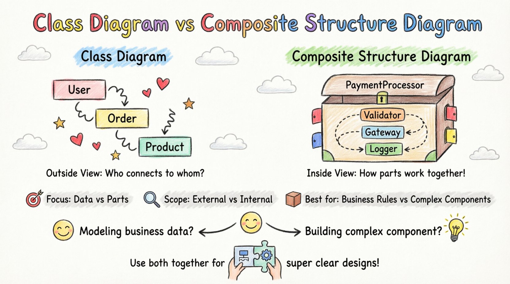
When an architect needs to answer questions like “What data does an Order hold?” or “How does a User interact with a Product?”, the Class Diagram is the standard tool. It focuses on the identity and static properties of entities rather than their internal mechanical behavior.
Understanding the Composite Structure Diagram 🧩
The Composite Structure Diagram (often called a Component Structure Diagram in earlier specifications) offers a more granular view. It describes the internal structure of a classifier. Instead of just showing the class itself, it shows the parts that make up the class and how they interact.
Core Components
- Part: A named portion of the classifier’s internal structure.
- Role: A named interface or responsibility that a part fulfills within the composite structure.
- Port: A specific point of interaction where a part connects to the external environment or other parts.
- Interface: A contract defining the operations available at a port.
- Connector: A link that binds a provided interface to a required interface.
Primary Use Cases
Composite Structure Diagrams are best suited for:
- Modeling complex components with internal logic.
- Designing embedded systems or hardware-software co-design.
- Specifying delegation mechanisms (how a class delegates work to its parts).
- Visualizing microservice architectures or modular subsystems.
- Defining strict boundaries for component interaction.
This diagram answers questions like “What internal modules make up this processor?” or “How does the input data flow through the internal filters before reaching the output?”. It shifts focus from the entity to the mechanism.
Key Differences at a Glance 🔄
To clarify the distinction, we can compare the two diagrams across several dimensions. The following table outlines the technical divergence.
| Feature | Class Diagram | Composite Structure Diagram |
|---|---|---|
| Scope | External structure and relationships between classes. | Internal structure of a single classifier. |
| Focus | Data, attributes, and static associations. | Parts, ports, roles, and internal interactions. |
| Complexity | High-level domain modeling. | Low-level component implementation details. |
| Interaction | Implicit through method calls. | Explicit via Ports and Connectors. |
| Best For | Domain logic and database schema. | Component architecture and hardware integration. |
Strategic Selection Framework 🧭
Deciding which diagram to employ depends on the specific phase of the system analysis and the level of abstraction required. Below is a decision matrix based on common engineering scenarios.
Scenario 1: Domain Modeling
If the goal is to capture the business rules and data relationships, the Class Diagram is the appropriate choice. It allows analysts to define entities like Customer, Invoice, and Payment without worrying about how the internal code handles them.
- Why: Business stakeholders understand classes and attributes better than ports and connectors.
- Outcome: A clear schema for database generation and API definition.
Scenario 2: Component Integration
When designing a system where distinct modules must communicate strictly, the Composite Structure Diagram excels. It defines the contract (interface) at the boundary of the component.
- Why: It prevents tight coupling by enforcing interaction through defined ports.
- Outcome: A modular architecture where internal changes do not break external dependencies.
Scenario 3: Hardware-Software Co-Design
In embedded systems, a class might represent a physical device. A Class Diagram cannot effectively show the internal sensors or actuators that constitute the device.
- Why: Composite Structure Diagrams allow modeling of physical parts (e.g., CPU, RAM, Sensor) within a single logical unit.
- Outcome: Accurate mapping of software logic to physical hardware constraints.
Scenario 4: Algorithmic Flow within a Class
Sometimes a single class contains complex logic that involves multiple sub-objects working together. A Class Diagram shows the class as a black box. A Composite Structure Diagram opens that box.
- Why: It reveals the delegation chain. For example, a PaymentProcessor class might delegate validation to a Validator part and execution to a Gateway part.
- Outcome: Clearer understanding of responsibility distribution.
Implementation Implications 💻
The choice of diagram has direct consequences for the code generation and maintenance lifecycle. Understanding these implications helps in justifying the modeling effort.
Code Generation from Class Diagrams
Class diagrams are highly conducive to forward engineering. Most modeling tools can generate boilerplate code for classes, including getters, setters, and relationship logic. However, this generation assumes that the internal logic of the class is straightforward.
- Pros: Rapid scaffolding of object-oriented code.
- Cons: May oversimplify internal complexity, leading to “God Classes” where one class does too much.
Code Generation from Composite Structure Diagrams
When using Composite Structure Diagrams, the focus shifts to component composition. Code generation involves creating the container class and the internal parts as distinct classes or modules.
- Pros: Enforces separation of concerns. The container class becomes a facade that manages internal parts.
- Cons: Higher initial setup cost. Requires careful management of interface definitions.
Refactoring and Maintenance
As systems evolve, diagrams must be updated. Class diagrams often become cluttered as relationships multiply. Composite Structure Diagrams can be more resilient to change because internal parts can be swapped if they adhere to the same port contract.
- Stability: Composite diagrams protect the external interface from internal refactoring.
- Visibility: They make hidden dependencies visible, reducing technical debt.
Common Pitfalls to Avoid ⚠️
Even with the right tool, modeling errors can occur. Awareness of common mistakes ensures the diagrams remain valuable assets rather than documentation burdens.
Pitfall 1: Mixing Levels of Abstraction
Do not attempt to show internal component logic within a Class Diagram if the complexity warrants a Composite Structure Diagram. Conversely, do not use Composite Structure Diagrams to model simple data entities. This creates confusion for readers who expect different levels of detail.
Pitfall 2: Over-Modeling Relationships
Class diagrams can easily become spaghetti diagrams. Limit the number of associations shown on a single page. If a class has too many connections, consider breaking it down or using a Composite Structure Diagram to encapsulate those relationships internally.
Pitfall 3: Ignoring Interface Contracts
When using Composite Structure Diagrams, the ports and interfaces must be explicitly defined. Vague connections lead to implementation errors. Every port should have a clear provided or required interface.
Pitfall 4: Static vs. Dynamic Confusion
Both Class and Composite Structure diagrams are static. They do not show runtime behavior, flow, or state changes. Do not use them to explain *how* data moves over time; use Sequence or Activity diagrams for that. These structural diagrams define *what* exists, not *what happens*.
Integrating Both Diagrams 🔗
It is rarely an either/or situation. In a robust system architecture, both diagrams serve complementary roles. A typical documentation suite might contain:
- High-Level View: A Class Diagram showing the domain entities and their associations.
- Component View: A Composite Structure Diagram detailing the implementation of a critical, complex class.
- Interface View: Interfaces defined in the Composite Structure Diagram referenced in the Class Diagram.
This layered approach allows different teams to work at their required level of detail. The backend team might focus on the Class Diagram for database schema, while the frontend team focuses on the Composite Structure Diagram for API boundary definitions.
Final Considerations 🎯
Selecting between a Class Diagram and a Composite Structure Diagram is a decision driven by the complexity of the system and the specific questions being asked. The Class Diagram remains the default for defining the domain and static relationships. It is the language of the data model.
The Composite Structure Diagram becomes necessary when the internal mechanics of a class matter. It is the language of the component architecture. By understanding the strengths of each, architects can produce models that are both accurate and actionable.
Effective modeling reduces ambiguity. It aligns the vision of the business with the reality of the code. Whether choosing the broad strokes of a Class Diagram or the internal detail of a Composite Structure Diagram, the goal remains the same: clarity, maintainability, and robust system design.
Continuously evaluate the necessity of each diagram. If a diagram does not add value to the understanding of the system, it should be revised or removed. Keep the documentation lean, precise, and focused on the structural truths of the system.