Understanding the architecture of complex software systems requires more than just writing code. It demands a clear visualization of how components interact and how they behave over time. In the Unified Modeling Language (UML), the Composite Structure Diagram plays a pivotal role in defining the internal architecture of classifiers. However, this static representation often needs to be complemented by dynamic behavioral models to provide a complete picture of system functionality.
This guide explores the distinction between static structural views and dynamic behavioral models within the context of Composite Structure Diagrams. We will examine how these elements interact, why separating them is crucial for clarity, and how to utilize both effectively in system design.
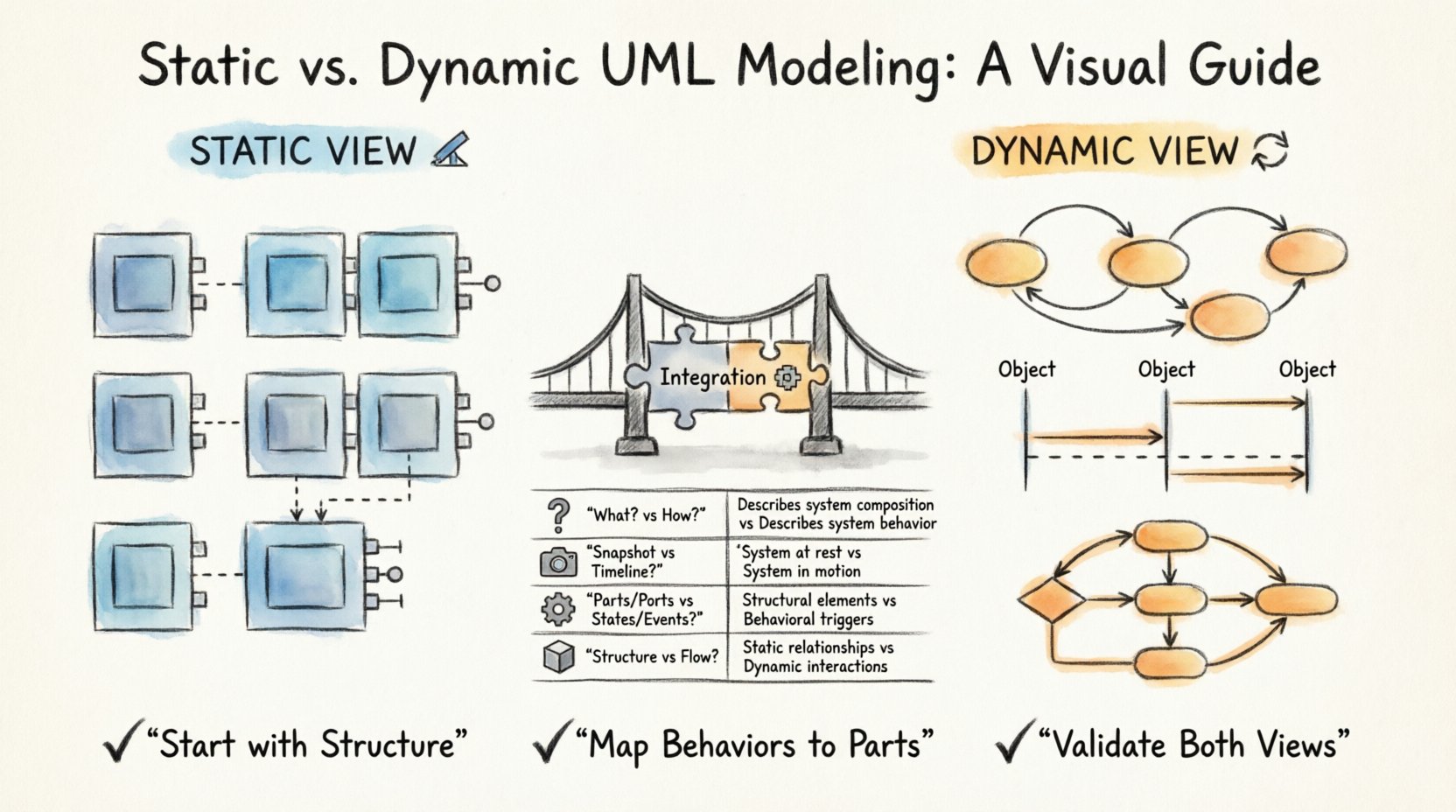
Understanding the Composite Structure Diagram 🏗️
The Composite Structure Diagram is a specialized type of UML diagram. It focuses on the internal structure of a classifier. Unlike a standard Class Diagram, which shows relationships between classes, this diagram exposes the parts that make up a class or component. It reveals how these parts are connected and what interfaces they expose.
Think of this diagram as an X-ray of a specific class. It allows architects to see the guts of a system element without getting lost in implementation details immediately. The primary purpose is to show:
- Parts: The internal components that comprise the classifier.
- Roles: The responsibilities assigned to each part.
- Interfaces: The points of interaction between parts.
- Connectors: The links that allow data or control flow between parts.
While powerful, the Composite Structure Diagram represents a snapshot. It captures the system at a specific moment in time. It does not show movement, state changes, or the sequence of operations. This limitation necessitates the use of dynamic behavioral models.
The Static View: Structure and Composition 📐
Static views describe the architecture of the system. They answer the question: “What is the system made of?”. In the context of Composite Structure Diagrams, the static view is concerned with the physical or logical arrangement of components.
Key Components of Static Structure
To fully grasp the static aspect, one must understand the specific elements used in these diagrams:
- Classifiers: The outer shell of the diagram, representing the whole entity.
- Part: An instance of a classifier that is owned by another classifier. It is a static relationship.
- Port: A designated point on a classifier where interactions can occur. It defines the boundary.
- Connector: Links two ports together, establishing a communication channel.
- Interface: Defines a set of operations provided or required by a part.
- Collaboration: A group of elements that work together to provide a specific functionality.
The Role of Deployment Nodes
Although often associated with Deployment Diagrams, Composite Structure Diagrams can include nodes to show where parts are deployed. This static view helps in understanding resource allocation and physical boundaries. It defines the topology of the system without defining the flow of data through that topology.
When modeling statically, the focus is on:
- Defining ownership relationships.
- Establishing interfaces for interaction.
- Identifying internal connections.
- Ensuring all parts have defined roles.
This level of detail is essential for code generation and understanding the physical constraints of the software. It sets the stage for behavior but does not describe it.
The Dynamic View: Behavioral Models 🔄
Dynamic views describe the behavior of the system. They answer the question: “How does the system act?”. While the Composite Structure Diagram shows the skeleton, dynamic models show the muscles and nerves in motion.
Types of Behavioral Models
Several UML diagrams fall under the category of dynamic behavioral models. Each serves a unique purpose in describing system actions:
- State Machine Diagrams: Describe how an object changes state in response to events. This is critical for understanding the lifecycle of a component.
- Activity Diagrams: Show the flow of control or data from activity to activity. They resemble flowcharts and are useful for business processes.
- Sequence Diagrams: Illustrate how objects interact with each other over time. They focus on message passing.
- Communication Diagrams: Similar to sequence diagrams but emphasize the structural organization of objects.
Interaction with Structure
Dynamic models do not exist in a vacuum. They rely on the static structure defined in the Composite Structure Diagram. For instance, a State Machine Diagram will define states for a specific Part defined in the static view. A Sequence Diagram will show messages sent between Ports.
Without the static definition, dynamic models lack context. Without dynamic models, static definitions lack life. The integration of both provides a comprehensive view of the system.
Comparing Static and Dynamic Approaches 🆚
To clarify the distinctions, we can analyze the two approaches side by side. The following table highlights the core differences in purpose, focus, and output.
| Feature | Static View (Composite Structure) | Dynamic Behavioral Models |
|---|---|---|
| Primary Question | What is the system composed of? | How does the system operate? |
| Time Dimension | Atemporal (Snapshot) | Temporal (Over Time) |
| Focus | Structure, Composition, Interfaces | State, Flow, Interactions |
| Key Elements | Parts, Ports, Connectors | States, Events, Activities |
| Validation | Verifies integrity and connectivity | Verifies logic and response |
| Use Case | Architecture design, Component definition | Process flow, User interaction logic |
Integrating Structure and Behavior 🧩
Effective modeling requires bridging the gap between structure and behavior. You cannot simply draw a diagram and expect it to function correctly in the real world. The integration process involves mapping behavioral logic onto structural components.
Mapping States to Parts
When a Part in a Composite Structure Diagram changes its internal state, it is often represented in a State Machine Diagram. The state machine defines valid transitions for that part. This ensures that the behavior is constrained by the structure. For example, a database connection part can only enter a “Connected” state if the connector is active.
Defining Protocols on Ports
Ports often have protocols that dictate what messages can be sent or received. These protocols are essentially behavioral rules attached to structural elements. By defining these rules, you ensure that dynamic interactions adhere to the static contract.
Validation Through Tracing
Tracing allows modelers to follow a specific behavior back to the structural elements that support it. If a sequence of events fails, the modeler can trace it to a specific part or port to identify structural issues. This bidirectional tracing is vital for debugging and maintenance.
Common Modeling Challenges ⚠️
Even with clear definitions, combining static and dynamic views presents challenges. Understanding these pitfalls helps in creating more robust models.
1. Overcomplicating the Static View
Adding too many parts to a single classifier can make the Composite Structure Diagram unreadable. It is better to break down complex classes into smaller, manageable units. If a diagram becomes too crowded, consider using nested structures or splitting the model into sub-packages.
2. Ignoring State Constraints
Behavioral models often assume that any interaction is possible. However, static structures impose constraints. A part may not be able to accept a message if it is in a specific state. Failing to document these constraints leads to logical errors in implementation.
3. Disconnecting Ports from Logic
Ports define where interaction happens, but they do not define how it happens. If the behavioral logic is not explicitly linked to the port, developers may implement logic in the wrong place. Always ensure that the State Machine or Activity Diagram explicitly references the owning part.
4. Redundant Information
Repeating the same information in both static and dynamic diagrams can lead to maintenance issues. If a part is renamed in the structure, all behavioral diagrams must be updated. Use references and cross-referencing to minimize duplication.
Guidelines for Accurate Modeling 📝
To ensure high-quality diagrams, follow these established guidelines. These practices help maintain consistency between the static blueprint and the dynamic behavior.
- Start with Structure: Define the parts and interfaces before detailing the behavior. The behavior belongs to the structure.
- Keep Interfaces Abstract: Define interfaces based on contracts, not implementations. This allows behavior to change without breaking the structure.
- Use Naming Conventions: Ensure that part names in the static diagram match the object names in the dynamic diagrams.
- Validate Connectivity: Ensure every port has a defined connector or is intentionally left open for external interaction.
- Document Lifecycle: Use State Machine Diagrams to show how parts are created, used, and destroyed.
- Review Regularly: Architecture evolves. Regular reviews ensure the static and dynamic views remain synchronized.
Why This Distinction Matters 🧠
The separation of static and dynamic views is not just academic. It has practical implications for software development and maintenance.
Facilitating Communication
Stakeholders often have different interests. Architects focus on the structure, while business analysts focus on the process. Clear separation allows each group to look at the diagram relevant to their needs without being overwhelmed by irrelevant details.
Supporting Code Generation
Modern model-driven development tools rely on these diagrams to generate code. Static diagrams generate class structures and interfaces. Dynamic diagrams generate methods and control logic. Confusing the two can lead to malformed code or missing functionality.
Enabling Scalability
As systems grow, the complexity of static structures increases. Dynamic behaviors can become exponential. By keeping them distinct, teams can manage complexity more effectively. They can refactor behavior without altering the core structure, or vice versa.
Practical Implementation Steps 🛠️
When beginning a project, follow a structured approach to modeling. This ensures that both views are developed cohesively.
- Identify Core Components: Determine the main classes or components of the system.
- Define Internal Parts: Break down complex components into their internal parts using the Composite Structure Diagram.
- Specify Interfaces: Define the ports and interfaces for communication.
- Map Behaviors: Create State Machine or Activity Diagrams for key parts.
- Connect Dynamics: Link the behaviors to the specific ports and parts.
- Review and Refine: Check for consistency between the structural layout and the behavioral flow.
Summary of Key Takeaways 📌
The relationship between static views and dynamic behavioral models is foundational to effective system modeling. The Composite Structure Diagram provides the necessary context for behavior to occur. It defines the boundaries, the connections, and the components.
Dynamic models fill in the gaps by describing the sequence of events, state changes, and interactions. Together, they form a complete specification of the system. Ignoring one in favor of the other leads to incomplete documentation and potential implementation errors.
By adhering to the guidelines outlined in this guide, modelers can create systems that are both structurally sound and behaviorally robust. This disciplined approach supports long-term maintainability and clarity in complex software environments.
Remember that diagrams are tools for thought. They help you understand the problem before you solve it. Using the right combination of static and dynamic views ensures that your solution is built on a solid foundation.