Understanding the internal structure of complex systems is a fundamental requirement for any robust software architecture. When moving beyond simple class relationships or sequence interactions, the need to visualize how components are composed and how they interact internally becomes critical. The Composite Structure Diagram serves this specific purpose within the Unified Modeling Language (UML) framework. It provides a detailed view of the internal organization of a classifier, revealing the parts that make up the whole and the connections between them. For an analyst tasked with documenting or validating system design, relying on memory or informal sketches is insufficient. A structured approach ensures clarity, consistency, and maintainability.
This guide outlines the 10 essential elements that must be present or explicitly considered when constructing a Composite Structure Diagram. By adhering to these criteria, you ensure that the diagram accurately reflects the system’s architecture without ambiguity. We will explore the definition of each element, its role in the diagram, and the implications of omitting it. This checklist is designed to aid in the rigorous analysis of system internals, ensuring that every connection and component is accounted for.
Why the Composite Structure Diagram Matters 🏗️
Before diving into the specific elements, it is important to understand the context in which this diagram operates. Unlike a Class Diagram, which focuses on static attributes and methods, or a Component Diagram, which focuses on deployment and high-level software modules, the Composite Structure Diagram zooms in on the internal makeup of a single classifier. It answers the question: “What is inside this class or component?”
It is particularly useful when a class is composed of other objects that collaborate to fulfill its responsibilities. For example, a Car classifier might contain an Engine, Transmission, and SteeringSystem as internal parts. The diagram shows how these parts are connected and how the Car exposes functionality to the outside world through its ports.
- Clarity: Removes ambiguity about internal composition.
- Traceability: Links internal parts to external interfaces.
- Validation: Helps verify that all dependencies are accounted for.
- Communication: Provides a visual language for developers and stakeholders.
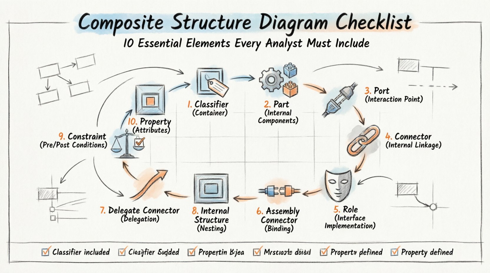
The 10 Essential Elements Checklist ✅
To ensure a diagram is complete and technically accurate, the following elements must be evaluated. Each item on this list represents a structural requirement. If an element is missing where it should exist, the diagram may misrepresent the system’s behavior or data flow.
1. The Classifier (The Container) 📦
Every Composite Structure Diagram must begin with a primary classifier. This is the element whose internal structure is being described. It acts as the container for all other elements within the diagram. In UML terms, this is often a Class, Component, or Node.
- Identification: The classifier must have a clear name.
- Type: It must be clearly identified as the subject of the structure.
- Scope: Ensure it matches the scope of the analysis. Do not mix unrelated classifiers in the same diagram unless showing a containment hierarchy.
If the classifier is not clearly defined, the entire diagram loses its anchor. The internal parts are meaningless without knowing which classifier owns them. Ensure the classifier is labeled with its full name and, if applicable, its package namespace.
2. Part (Internal Components) 🔧
Parts represent the objects that reside inside the classifier. These are the building blocks that work together. A part is a property of the classifier that has a specific type.
- Multiplicity: Define how many instances of the part exist (e.g., 0..1, 1, 0..*). This is crucial for understanding resource allocation.
- Type: The part must reference a valid classifier or component type.
- Visibility: Indicate if the part is visible to the outside world or strictly internal.
When documenting parts, avoid creating a generic “Part” label. Use specific names that reflect the role of the component. For instance, instead of “Part1”, use “FuelInjector”. This reduces cognitive load for anyone reading the diagram later.
3. Port (Interaction Point) 🔌
Ports are the interaction points of the classifier. They define how the internal parts communicate with the external environment or with other internal parts. A port encapsulates the interface that the classifier offers or requires.
- Provided Interface: A port where the classifier offers services to the outside.
- Required Interface: A port where the classifier needs services from the outside.
- Named Ports: Every port should ideally have a unique name to avoid confusion.
Without ports, the diagram fails to show how the internal structure interacts with the rest of the system. A classifier with internal parts but no defined ports is effectively an isolated unit, which is rarely the case in distributed or modular systems.
4. Connector (Internal Linkage) 🔗
Connectors define the links between parts, ports, and roles. They represent the flow of data or control signals between the internal components. In a Composite Structure Diagram, connectors are distinct from association lines in Class Diagrams because they represent physical or logical wiring within the structure.
- Source and Target: Clearly define which element connects to which.
- Type of Connection: Specify if it is a data flow, control flow, or signal.
- Role Names: Assign role names to the ends of connectors to describe the function of the connection.
Connectors are the veins of the diagram. They show how the parts collaborate. A missing connector implies that two parts cannot communicate, which might be a design flaw or an intentional isolation that needs documentation.
5. Role (Interface Implementation) 🎭
A role is a representation of an interface implemented by a part. When a part connects to a port, it plays a specific role. This distinguishes the abstract interface from the concrete implementation.
- Interface Reference: The role should reference the specific interface being implemented.
- Multiplicity: Define how many interfaces of this type are played.
- Binding: Roles are bound to ports or other connectors.
Roles allow for polymorphism in the diagram. The same interface can be played by different parts, or the same part can play different roles. This flexibility is key to understanding complex system behaviors without cluttering the diagram with too many direct connections.
6. Assembly Connector (Binding) 🔌
An Assembly Connector is a specific type of connector that binds a required interface to a provided interface. It represents a contract fulfillment. If a part requires a service, and another part provides it, the assembly connector links them.
- Binding Point: Indicates where the connection is made.
- Interface Match: Ensure the provided interface matches the required interface type.
- Completeness: Verify that all required interfaces have a matching provided interface within the scope.
This element is critical for dependency management. It shows exactly where dependencies are resolved. If a required interface has no assembly connector, the system will fail at runtime. This element helps analysts identify missing dependencies early.
7. Delegate Connector (Delegation) 🏃
A Delegate Connector allows the external interface of the classifier to be delegated to an internal part. This means a call to the classifier’s port is automatically routed to a specific internal part’s port.
- Routing Logic: Shows how external requests are handled internally.
- Transparency: Hides the internal complexity from the external caller.
- Mapping: Clearly maps the external port to the internal part’s port.
Delegate connectors simplify the view of the system. They allow the classifier to act as a proxy. Without this, the external world would need to know exactly which internal part to call, breaking encapsulation.
8. Internal Structure (Nesting) 🪆
Composite structures can be nested. A part can itself be a classifier with its own internal structure. This allows for hierarchical modeling of complex systems.
- Depth: Be careful with nesting depth. Too many levels can make the diagram unreadable.
- Consistency: Ensure nested structures follow the same rules as the parent.
- Scope: Clearly define which diagram shows which level of nesting.
Nesting is powerful but should be used judiciously. It is often better to create separate diagrams for deeply nested structures rather than cluttering a single view. However, when necessary, the internal structure element must be clearly marked to show the containment hierarchy.
9. Constraint (Pre/Post Conditions) ⚖️
Constraints define the rules that govern the behavior or structure of the elements. In UML, these are often expressed using Object Constraint Language (OCL) or natural language notes.
- Validity: Rules that must be true for the diagram to be valid.
- Behavior: Rules that describe how the system behaves under certain conditions.
- Placement: Constraints should be attached to the relevant element.
Constraints prevent invalid configurations. For example, a constraint might state that a specific part must always have a value greater than zero. Including constraints ensures that the diagram captures not just the structure, but the logic governing that structure.
10. Property (Attributes) 📝
Properties are the data attributes of the classifier or its parts. While often shown in Class Diagrams, they are relevant here to show the state of the internal parts.
- Data Types: Specify the type of data stored in the property.
- Default Values: Indicate if a property has a default initialization.
- Read/Write Access: Define if the property is mutable or constant.
Properties provide context for the state of the system. Knowing that a part has a property like Temperature or Status helps in understanding how that part contributes to the overall behavior. Ensure properties are consistent with the interface definitions.
Validation Table for Analysts 📊
Use the following table to review your Composite Structure Diagram before finalizing it. This checklist helps ensure that all 10 elements are properly addressed and validated.
| Element | Checklist Item | Validation Criteria |
|---|---|---|
| Classifier | Is the main classifier named? | Name is unique and matches the system context. |
| Part | Are all internal parts defined? | Every physical or logical component is listed. |
| Port | Are interaction points defined? | Provided and required interfaces are visible. |
| Connector | Are internal links drawn? | All necessary connections between parts exist. |
| Role | Are interfaces implemented? | Parts play specific roles matching their interfaces. |
| Assembly Connector | Are dependencies bound? | All required interfaces have provided matches. |
| Delegate Connector | Is delegation mapped? | External calls are routed to internal parts. |
| Internal Structure | Is nesting handled? | Deep hierarchies are split or clearly labeled. |
| Constraint | Are rules documented? | Business logic is attached to relevant elements. |
| Property | Are attributes listed? | State data types are defined for parts. |
Integration with Other Diagrams 🔄
A Composite Structure Diagram does not exist in isolation. It is part of a larger ecosystem of modeling artifacts. Ensuring consistency with other diagrams is vital for a coherent system design.
Relationship with Class Diagrams
Class Diagrams show the static structure of the system at a high level. Composite Structure Diagrams dive deeper into the composition of specific classes. The parts in a Composite Structure Diagram should correspond to the associations or aggregations in the Class Diagram. If a Class Diagram shows a composition relationship, the Composite Structure Diagram should visualize the internal layout of that composition.
Relationship with Sequence Diagrams
Sequence Diagrams show the dynamic flow of messages. The ports and connectors in the Composite Structure Diagram should align with the message exchanges in the Sequence Diagram. If a Sequence Diagram shows a message being sent to a port, that port must exist in the Composite Structure Diagram. This alignment ensures that the static structure supports the dynamic behavior.
Relationship with Component Diagrams
Component Diagrams focus on the deployment and high-level modules. A Composite Structure Diagram might be used to detail the internal structure of a single component from the Component Diagram. Ensure that the classifiers in the Composite Structure Diagram map back to the components defined at the higher level.
Common Errors and Pitfalls ⚠️
Even with a checklist, errors can occur during the modeling process. Being aware of common pitfalls helps in avoiding them.
- Over-complication: Trying to show the entire system in one diagram. Keep the scope focused on a single classifier.
- Missing Multiplicity: Forgetting to specify how many parts exist. This leads to ambiguity in resource planning.
- Unclear Interfaces: Using generic names for ports instead of specific interface names.
- Disconnected Parts: Parts that are defined but not connected to any port or other part. These are orphaned elements.
- Inconsistent Notation: Mixing different UML notations or symbols within the same diagram.
Maintaining the Diagram 🛠️
Once the diagram is created, it must be maintained. Systems evolve, and the diagram must evolve with them.
- Version Control: Store diagrams alongside code or requirements documents.
- Review Cycle: Schedule regular reviews to ensure the diagram matches the current implementation.
- Change Management: When a part is added or removed, update the diagram immediately.
- Documentation: Include notes explaining complex connections or business rules.
Maintaining accuracy is more important than creating a perfect diagram once. A diagram that is out of date is worse than no diagram at all. Regular updates ensure that the diagram remains a useful tool for analysis and communication.
Final Thoughts on Structural Analysis 🧠
Creating a robust Composite Structure Diagram requires attention to detail and a deep understanding of the system’s internal logic. By including the 10 essential elements listed in this guide, you provide a clear and accurate representation of the classifier’s composition. This clarity benefits developers, testers, and stakeholders alike.
Remember that the goal is not just to draw a picture, but to communicate the architecture effectively. Each element serves a specific purpose in defining the boundaries, interactions, and dependencies of the system. When these elements are present and correctly defined, the diagram becomes a reliable reference for the lifecycle of the software. Focus on consistency, clarity, and completeness to ensure the highest quality of analysis.