Creating a UML sequence diagram is an essential skill for software architects and developers. These diagrams visualize the interaction between objects over time. They serve as a blueprint for system behavior, helping teams understand how data flows and how components collaborate. However, even experienced practitioners often introduce subtle errors that can lead to misinterpretation during implementation.
A well-constructed diagram reduces ambiguity. It ensures that everyone from backend engineers to frontend developers shares the same mental model. When diagrams contain inaccuracies, the risk of bugs increases, and development time extends. This guide addresses frequent pitfalls in sequence diagramming and provides actionable corrections. We will examine lifelines, message types, activation bars, and interaction fragments. By adhering to these standards, you ensure your technical documentation remains clear and reliable.
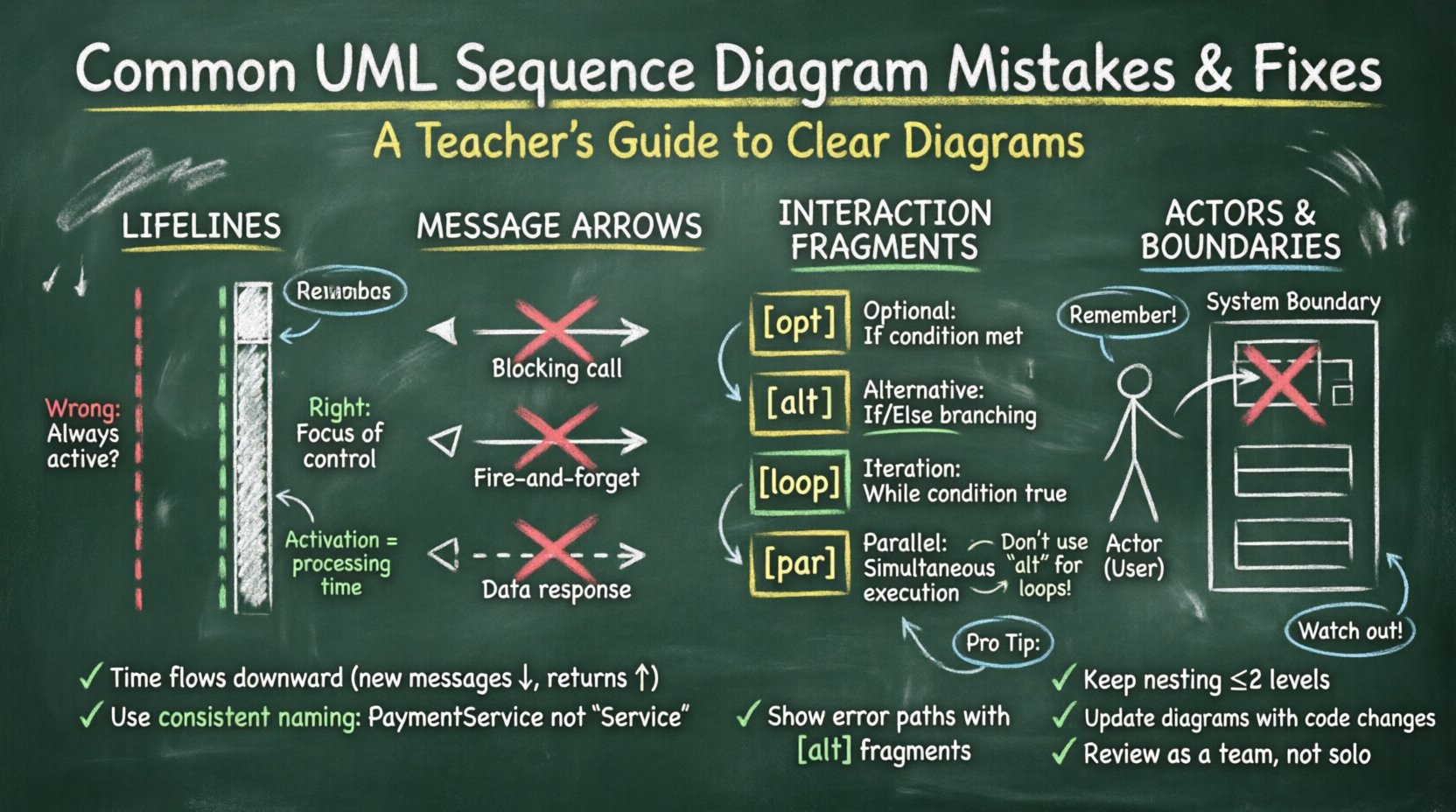
1. Lifeline Errors: Scope and Deactivation 📉
The lifeline represents a participant in the interaction. It is a vertical dashed line extending from the top of the diagram to the bottom. Errors here often stem from misunderstanding when an object is active versus when it is waiting.
❌ The Mistake: Missing Deactivation Bars
Many diagrams show a continuous line from top to bottom without interruption. This implies the object is active for the entire duration of the sequence. In reality, objects wait for messages and process them briefly before returning to an idle state.
- Impact: Readers assume the object is performing background tasks continuously, which is rarely true.
- Impact: It becomes difficult to identify the specific time an object is busy processing logic.
✅ The Fix: Use Activation Bars
Insert a thin rectangle on the lifeline whenever the object is processing a message. This is the “focus of control.”
- Start Point: The top of the bar aligns with the incoming message arrowhead.
- End Point: The bottom of the bar aligns with the outgoing message arrowhead or the end of the operation.
- Idle State: When no activation bar is present, the object is passive.
❌ The Mistake: Overlapping Lifelines
Placing lifelines too close together creates visual clutter. It also makes it hard to trace which message belongs to which object.
- Fix: Maintain consistent horizontal spacing between participants. If the diagram is wide, consider using multiple frames or splitting the interaction logically.
2. Message Flow Confusion: Direction and Type 📬
Messages represent the communication between objects. The arrow type indicates the nature of the call. Incorrect arrow styles change the meaning of the interaction.
❌ The Mistake: Confusing Synchronous and Asynchronous Calls
Synchronous calls (solid line, filled arrowhead) block the sender until a response is received. Asynchronous calls (solid line, open arrowhead) do not block the sender.
- Common Error: Using filled arrows for background tasks like logging or notifications.
- Consequence: Developers might implement blocking logic where non-blocking logic is required, causing performance bottlenecks.
✅ The Fix: Strict Arrow Definitions
Define a standard for your team regarding arrow types.
- Sync Call: Solid line, filled triangle. Use for operations requiring an immediate return value or state change before continuing.
- Async Call: Solid line, open triangle. Use for fire-and-forget tasks.
- Return Message: Dashed line, open arrowhead. Always show the return path if the operation yields data. If the return is void or implied, omit it to reduce clutter.
❌ The Mistake: Ignoring Return Messages
Some diagrams only show the outgoing message. This hides the data flow back to the requester.
- Why it matters: A sequence diagram is not just a control flow; it is a data flow. Missing returns obscure what information is available at each step.
- Fix: Draw the return arrow for every operation that produces a value.
3. Interaction Fragments: Logic and Operators 🔄
p>Combined fragments allow you to express complex logic like loops, conditionals, and optional steps. Using the wrong operator is a frequent source of ambiguity.❌ The Mistake: Using “alt” for Iteration
The alt (alternative) fragment is for mutually exclusive choices (If/Else). It is often mistakenly used to show a loop.
- Error: Showing the same block of messages multiple times within an
altframe. - Consequence: It implies the system branches into different states, not repeats the same state.
✅ The Fix: Correct Fragment Operators
- opt (Optional): Use when a step might not happen at all. Label the condition clearly (e.g., [User is Admin]).
- alt (Alternative): Use for branching logic. Ensure conditions cover all possibilities if it is a definitive path.
- loop (Iteration): Use when a process repeats. Add a guard condition if the loop has a limit (e.g., [while item exists]).
- par (Parallel): Use when messages occur simultaneously. This is distinct from concurrency in code but represents logical overlap in time.
❌ The Mistake: Nested Fragments Without Limits
Deeply nesting frames makes the diagram unreadable. A loop inside a loop inside an alternative creates a visual maze.
- Fix: Keep nesting to a maximum of two levels. If logic is more complex, break it into separate diagrams or sub-sequences.
4. Actors and External Systems 🤖
Diagrams often involve actors (users) or external systems (APIs, databases). Misrepresenting these boundaries leads to integration errors.
❌ The Mistake: Treating Actors as Internal Objects
Actors should be distinct from system objects. They exist outside the system boundary.
- Error: Drawing actors with the same shape as internal classes.
- Fix: Use the standard UML actor stick figure for human users. Use a boundary rectangle or distinct shape for external systems.
❌ The Mistake: Missing System Boundary
Without a clear boundary, it is unclear which messages cross the system limit.
- Fix: Draw a large rectangle enclosing the internal objects. Label it “System Name”. Messages crossing this line are external interfaces.
5. Readability and Documentation Standards 📝
A diagram is useless if the team cannot read it quickly. Clarity is as important as accuracy.
❌ The Mistake: Lack of Context
Diagrams often show a single message without context. The reader doesn’t know the precondition or the postcondition.
- Fix: Add a short description above the diagram explaining the scenario (e.g., “User attempts to reset password”).
- Fix: Use notes or comments to explain complex logic that cannot be shown with arrows.
❌ The Mistake: Inconsistent Naming
Using different names for the same object in different diagrams confuses the reader.
- Fix: Adopt a naming convention. Use “User” instead of “Customer” or “Client” consistently. Use full class names for objects (e.g.,
PaymentServiceinstead ofService).
❌ The Mistake: Time Violation
Time flows downwards. If a message appears higher than the message that triggered it, it implies a time paradox.
- Fix: Ensure all arrows point downwards relative to the trigger, except for return messages which point upwards.
- Check: Verify that the vertical position of the arrowhead matches the logical flow of time.
Comparison of Common Errors vs. Standards
| Area | Common Mistake | Correct Standard |
|---|---|---|
| Lifelines | Continuous line without breaks | Use activation bars for processing time |
| Messages | Missing return arrows | Dashed return arrows for data responses |
| Fragments | Using alt for loops |
Use loop for iterations |
| Actors | Same shape as internal objects | Stick figure for users, boundary for systems |
| Time | Upward arrows for new messages | New messages always downward |
| Names | Inconsistent object naming | Standardized class names across diagrams |
6. Maintenance and Evolution 🔄
Software changes. Requirements shift. A diagram that was accurate last month may be obsolete today. Neglecting to update diagrams creates technical debt.
❌ The Mistake: Outdated Documentation
Keeping a diagram for a feature that has been refactored. This misleads new team members.
- Strategy: Treat diagrams as living documents. Update them alongside code commits when the interaction logic changes.
❌ The Mistake: Over-Detailing
Trying to show every single database query in a high-level design diagram.
- Strategy: Use abstraction. Show the service call, not the SQL statement. Reserve detailed data flow for database schema diagrams.
7. Communication and Team Alignment 🗣️
The primary goal of a sequence diagram is communication. If the team disagrees on the meaning, the diagram has failed.
❌ The Mistake: Solo Creation
One developer creates the diagram without input from others. This leads to blind spots.
- Fix: Review diagrams in design meetings. Walk through the flow with stakeholders before implementation begins.
❌ The Mistake: Ignoring Error Paths
Diagrams often only show the “Happy Path” (everything works perfectly).
- Fix: Explicitly show error handling. If a service fails, how does the system respond? Use
optoraltto show exception handling flows.
8. Technical Semantics and UML Compliance 📐
While tools vary, the UML standard remains the foundation. Deviating from standard syntax makes diagrams hard to read for those using different tools.
❌ The Mistake: Custom Notations
Inventing new arrow styles or symbols not defined in the UML specification.
- Fix: Stick to standard arrows. If you must use custom logic, add a legend or note explaining the notation.
❌ The Mistake: Mixing Diagram Types
Putting object creation or destruction logic into a sequence diagram when a Class or State diagram is better suited.
- Fix: Use Sequence Diagrams for runtime interaction. Use Class Diagrams for static structure. Keep the scope focused.
9. Performance and Concurrency Considerations ⚡
Modern systems are often distributed. Sequence diagrams must reflect concurrency accurately.
❌ The Mistake: Linearizing Parallel Processes
Showing two parallel events as sequential steps.
- Fix: Use the
parfragment to denote simultaneous execution. This clarifies that the total time is not the sum of both steps.
❌ The Mistake: Ignoring Network Latency
Assuming immediate communication between distributed services.
- Fix: Add notes indicating network hops or timeouts if they impact the logic flow significantly.
10. Final Thoughts on Diagram Integrity 🎯
Building accurate UML sequence diagrams requires discipline. It is not enough to draw lines; you must understand the semantics behind them. By correcting these common mistakes, you improve the quality of your software architecture documentation.
Focus on clarity. Ensure that every arrow has a purpose. Verify that time flows logically. Keep your terminology consistent. These habits will save your team time during development and debugging. A clear diagram is a contract between the design and the implementation. Honor that contract with precision.
- Review: Regularly audit your diagrams against the code.
- Standardize: Define rules for your team regarding notation.
- Collaborate: Use diagrams as a discussion tool, not just a deliverable.
When you eliminate ambiguity, you reduce risk. Your team can focus on building features rather than deciphering design intent. This approach leads to more robust systems and faster delivery cycles.