
Systems engineering demands precision. As complexity grows, the gap between abstract requirements and concrete implementation widens. Systems Modeling Language (SysML) bridges this gap. It provides a standardized notation to describe, specify, design, and analyze systems. This guide walks you through constructing your initial SysML model, focusing on the underlying logic rather than specific tooling.
🧠 Understanding the SysML Foundation
Before drawing shapes, it is crucial to understand the purpose. SysML is a general-purpose modeling language derived from Unified Modeling Language (UML). It was designed specifically to address the needs of systems engineering. Unlike UML, which focuses heavily on software, SysML accommodates hardware, software, data, and processes.
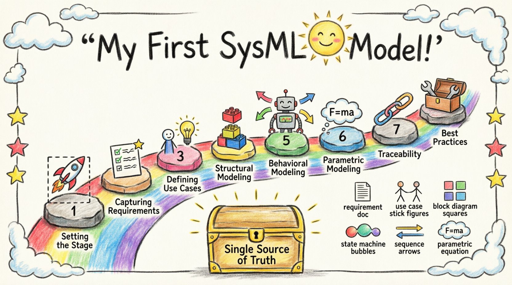
When you start building a model, you are creating a digital twin of the system under development. This allows for early validation and verification. The model serves as a single source of truth, reducing ambiguity across engineering teams.
Key Characteristics of SysML
Flexibility: Supports various viewpoints and perspectives.
Extensibility: Allows for custom profiles and extensions.
Traceability: Links requirements to design elements.
Interoperability: Exchanges data with other engineering tools.
🚀 Phase 1: Setting the Stage
The initial phase involves defining the scope. A model without boundaries becomes unmanageable. You must identify the system boundary. What is inside the system? What is outside?
Defining the System Boundary
Draw a rectangle to represent the system. Everything inside is controlled by the system. Everything outside is the environment or external interfaces. This distinction is vital for defining interfaces.
Internal Elements: Components, subsystems, and data stored within the system.
External Elements: Users, other systems, power sources, and environmental conditions.
Establishing the Viewpoint
Different stakeholders need different views. A project manager needs high-level progress. A designer needs interface definitions. An analyst needs performance metrics. Your model should support these views.
📋 Phase 2: Capturing Requirements
Requirements are the anchor of any engineering model. Without them, there is no criteria for success. SysML handles requirements using a dedicated diagram type.
Creating the Requirement Diagram
This diagram focuses solely on the needs the system must satisfy. It is not about how the system works, but what it must do.
Requirement Element: The basic unit of need. It has a unique ID and a description.
Constraints: Specific conditions that the requirement must meet.
Verification Method: How will you prove the requirement is met? (e.g., Test, Inspection, Analysis, Demonstration).
Organize requirements hierarchically. A top-level requirement might be “System shall operate in temperature range.” This breaks down into “Subsystem A shall operate in temperature range” and “Subsystem B shall operate in temperature range.”
Requirement Relationships
Requirements rarely exist in isolation. You need to define how they relate.
Relationship Type | Description |
|---|---|
Satisfy | A design element fulfills a requirement. |
Derive | A requirement is created from another requirement. |
Refine | A requirement is made more detailed or specific. |
Verify | A test case validates a requirement. |
🎯 Phase 3: Defining Use Cases
Once requirements are set, you must understand the interactions. Use cases describe how users or external systems interact with your system. This diagram clarifies the functional scope.
Identifying Actors
An actor represents an external entity. It could be a human operator, a software process, or another physical system. Do not confuse actors with internal components.
Primary Actor: The main initiator of the interaction.
Secondary Actor: A system that provides services to the primary system.
Mapping Use Cases
A use case represents a specific goal. For example, “Start System” or “Report Fault.” Connect actors to use cases with association lines. This visualizes who does what.
Extending and Including
Complex interactions often share common steps. Use Include to denote a mandatory step shared by multiple use cases. Use Extend for optional behavior that happens under specific conditions.
🧱 Phase 4: Structural Modeling
Structure defines the static anatomy of the system. SysML uses two primary diagrams for this: Block Definition Diagrams (BDD) and Internal Block Diagrams (IBD).
Block Definition Diagram (BDD)
The BDD is the high-level structure. It defines the types of parts that make up the system. Think of this as the blueprint or schema.
Blocks: Represent physical or logical parts.
Properties: Data attributes owned by the block (e.g., Mass, Voltage).
Operations: Functions the block can perform.
Relationships in BDD are crucial. They define how blocks relate to one another.
Relationship | Meaning |
|---|---|
Composition | Part of a whole. If the whole dies, the part dies. |
Aggregation | Part of a whole. Parts can exist independently. |
Generalization | Inheritance. One block is a specialized version of another. |
Internal Block Diagram (IBD)
While BDD defines types, IBD defines instances and connections. This is where you show how blocks fit together physically or logically.
Parts: Specific instances of blocks.
Ports: Entry and exit points for interaction.
Connectors: Links that pass information or energy between ports.
Define the flow of data, power, or material. This is essential for understanding the physical constraints of the design.
🔄 Phase 5: Behavioral Modeling
Structure is static. Behavior is dynamic. Systems change states and react to events. SysML offers several diagrams for this.
State Machine Diagram
Use this for components that have distinct modes of operation. A satellite, for example, might be in “Safe Mode,” “Orbit Mode,” or “Data Collection Mode.”
States: Conditions where the system remains.
Transitions: Movements from one state to another.
Events: Triggers that cause a transition.
Actions: Activities performed during a transition.
Sequence Diagram
This diagram shows interactions over time. It is ideal for complex message exchanges between multiple blocks.
Lifelines: Represent the participants in the interaction.
Messages: Arrows indicating communication.
Activation Bars: Show when a participant is actively processing.
Focus on the order of messages. Does the system wait for a response before proceeding? This diagram helps identify timing issues early.
⚙️ Phase 6: Parametric Modeling
Systems must satisfy physical constraints. Parametric diagrams allow you to model these constraints mathematically. This is where you define equations.
Defining Constraints
A constraint block represents an equation. You define variables within this block. For example, Newton’s Second Law (F = ma) can be modeled as a constraint.
Constraint Blocks: Encapsulate mathematical relationships.
Variables: Inputs and outputs of the constraint.
Equations: The logic governing the variables.
Solving the Model
Once constraints are linked to structural properties, the model becomes solvable. You can run simulations to check if design parameters meet requirements. For instance, does the calculated weight of the structure stay within the launch vehicle limit?
This step bridges the gap between abstract design and physical reality. It validates feasibility before physical prototyping begins.
🔗 Phase 7: Traceability and Verification
A model is only useful if you can navigate it. Traceability ensures that every design element links back to a requirement. This is critical for certification and safety.
Establishing Links
Link every requirement to the design element that satisfies it. If a requirement changes, you must know which parts of the model are affected. This is known as impact analysis.
Requirement to Block: Links functional needs to structural parts.
Block to Test: Links design elements to verification methods.
Use Case to Requirement: Links user goals to specific needs.
Checking Consistency
Automated checks can help identify inconsistencies. For example, does a port have a type defined? Is a variable used in an equation defined elsewhere? Consistency checks prevent errors from propagating.
🛠️ Phase 8: Best Practices for Model Maintenance
Models degrade over time if not maintained. As requirements evolve, the model must evolve with them. Follow these practices to keep the model healthy.
Modularization: Break the model into packages. Keep related diagrams together.
Naming Conventions: Use consistent names for blocks, ports, and requirements.
Documentation: Add notes to complex diagrams to explain the rationale.
Version Control: Treat the model like code. Track changes over time.
📈 Moving Forward
Building a SysML model is a skill that develops with practice. Start small. Define the requirements and the basic structure. Gradually add behavior and constraints as the design matures. The goal is not to create a perfect model immediately, but to create a useful one.
Remember that the model is a communication tool. It should make it easier for your team to understand the system, not harder. If a diagram confuses the reader, simplify it. Clarity is more important than complexity.
Summary of Key Diagrams
Requirement Diagram: What the system must do.
Use Case Diagram: How users interact with the system.
Block Definition Diagram: The high-level structure.
Internal Block Diagram: The internal connections.
State Machine Diagram: The modes of operation.
Sequence Diagram: The flow of messages.
Parametric Diagram: The physical constraints.
By adhering to these principles and following the structure outlined above, you will establish a robust foundation for systems engineering. The complexity of the system will dictate the depth of the model, but the discipline of the process remains constant.

