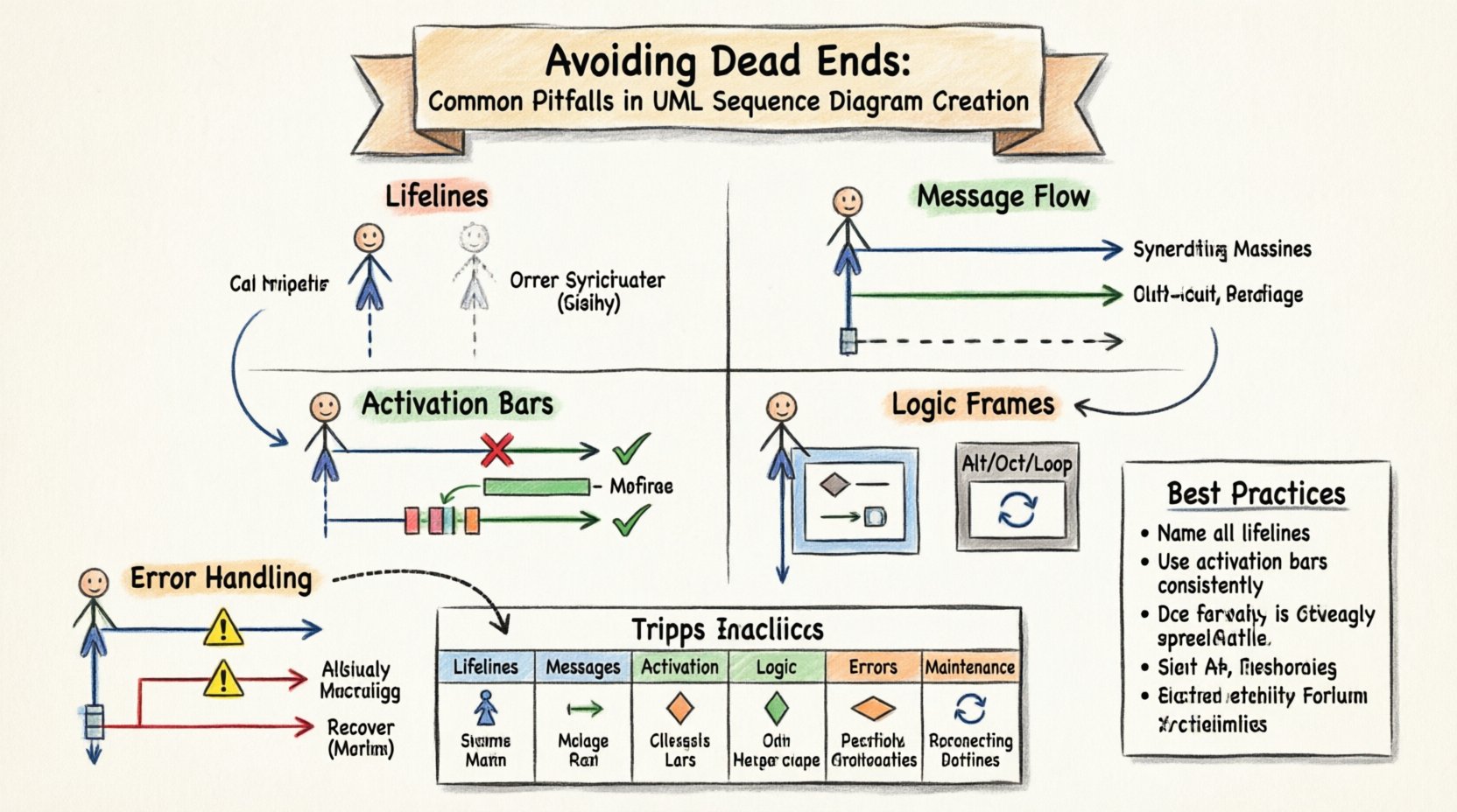
UML Sequence Diagrams serve as the backbone for visualizing system interactions. They translate abstract logic into a concrete timeline of communication between objects or actors. However, creating these diagrams often leads to ambiguity if not handled with precision. Many designers fall into traps that obscure the very logic the diagram is meant to clarify. This guide explores the critical errors that undermine the utility of sequence modeling and provides structured methods to ensure clarity.
🧱 The Foundation: Lifelines and Participants
The lifeline represents an individual participant in the interaction. It is the vertical line that anchors the diagram. When lifelines are defined incorrectly, the entire flow becomes disjointed. A common mistake is introducing participants that do not exist in the actual system architecture. This creates “phantom” dependencies that confuse developers during implementation.
- Undefined Scope: Including external systems without explicitly marking them as boundaries creates confusion about data ownership.
- Missing Actors: Omitting the initiating actor forces readers to guess the source of the request.
- Redundant Lifelines: Using multiple lifelines for the same object creates noise and makes tracing paths difficult.
Each lifeline must correspond to a specific class, interface, or external system component. If a component handles multiple distinct roles, consider splitting the lifeline or using a single lifeline with clear naming conventions. The goal is to map the diagram directly to the code structure.
💬 Message Flow and Interaction Types
Messages represent the communication between lifelines. They carry the data or commands that drive the system. Distinguishing between synchronous and asynchronous messages is a frequent source of error. Using the wrong arrow type implies incorrect execution timing.
Synchronous vs. Asynchronous
Synchronous messages block the sender until the receiver responds. Asynchronous messages do not wait for a response. Confusing these two alters the perceived performance and flow control of the system.
- Synchronous: Solid line with a filled arrowhead. The sender waits.
- Asynchronous: Solid line with an open arrowhead. The sender continues immediately.
- Return Message: Dashed line with an open arrowhead. This indicates a response returning to the caller.
A frequent pitfall is omitting return messages entirely. While not strictly required in every notation standard, omitting them hides the logic of data retrieval. If a method returns a value or a status code, a return message should be depicted. This clarifies where the data originates and how it propagates back up the call stack.
🔋 Activation Bars and Focus of Control
The activation bar, or focus of control, indicates when an object is actively executing a method. It appears as a thin rectangle on the lifeline. Misrepresenting this bar leads to misunderstandings about resource usage and thread blocking.
Common Activation Errors
- Starting Too Early: Extending the bar before the message arrives implies the object is busy before it receives the request.
- Ending Too Late: Keeping the bar active after the return message implies the object remains locked, potentially suggesting a deadlock or long-running process.
- Missing Activation: Omitting the bar for complex operations hides the duration of processing, making it hard to identify bottlenecks.
Correct activation bars help identify concurrency issues. If two activations overlap on the same lifeline, it suggests multithreading or parallel processing. If they do not overlap, the process is likely sequential. This visual cue is critical for performance analysis.
🔄 Handling Logic: Alt, Opt, and Loop Frames
Real-world systems rarely follow a single linear path. They branch based on conditions. UML provides frames like Alt (Alternative), Opt (Optional), and Loop to represent this logic. Misusing these frames creates diagrams that are either too complex or too vague.
Alt Frames: Alternatives
The Alt frame handles mutually exclusive paths. A common error is failing to label the conditions clearly. If the condition is implicit, the reader must guess the logic.
- Explicit Conditions: Always label the guard condition (e.g., [User is Admin], [Data Valid]).
- Completeness: Ensure all logical branches are covered. If a condition is false, where does the flow go?
- Redundancy: Avoid overlapping conditions that could result in multiple paths being taken simultaneously.
Loop Frames: Iteration
The Loop frame indicates repetition. A frequent mistake is drawing a loop that does not specify a termination condition. An infinite loop without a break condition suggests a system that never completes.
- Termination: Specify the condition that stops the loop (e.g., [while items exist]).
- Break Conditions: If a loop can be broken early, indicate that path explicitly.
- Scope: Ensure the loop frame encapsulates only the repeated interactions.
Opt Frames: Optionality
The Opt frame represents optional behavior. It is often confused with Alt. Opt is used when a path might not happen at all, whereas Alt is for when one of several paths must happen.
- Use Case: Use Opt for non-critical features like notifications or caching.
- Labeling: Label the condition as [if optional feature enabled].
❌ Error Handling and Exception Paths
Systems fail. A sequence diagram that only shows the “Happy Path” is incomplete and misleading. It gives a false sense of security regarding system stability. Error handling must be depicted to show how the system recovers or fails.
- Exception Messages: Show messages indicating errors (e.g., “Invalid Input”, “Timeout”).
- Catch Blocks: Indicate where exceptions are caught and handled locally versus where they propagate up.
- Recovery Steps: Show retry mechanisms or fallback procedures if available.
Ignoring error paths leads to production issues. Developers often implement the happy path first and treat errors as an afterthought. Visualizing exceptions early ensures robust architecture.
⏱️ Temporal Accuracy vs. Logical Abstraction
Sequence diagrams are not time charts. They represent logical order, not precise timing. However, the vertical positioning implies order. A common pitfall is over-specifying timing constraints without a valid reason.
- Order Matters: Messages appearing lower on the page happen later in the sequence.
- Concurrency: Parallel messages should be drawn on the same vertical level to indicate they happen simultaneously.
- Abstraction: Do not include micro-delays unless they are critical to the design (e.g., polling intervals).
Mixing logical order with specific timestamps often confuses the diagram. Keep the focus on the flow of control. If timing is critical, use a timing diagram instead. Mixing the two creates clutter.
🛠️ Maintenance and Evolution
Software changes. A sequence diagram created today may be obsolete tomorrow. One of the biggest pitfalls is creating diagrams that are too specific to the current implementation. They become difficult to update when requirements shift.
- Generic Interfaces: Use interfaces rather than concrete classes where possible to allow for implementation changes.
- Separation of Concerns: Split large diagrams into smaller, logical chunks. A single diagram with 50+ lifelines is unreadable.
- Versioning: Maintain a history of diagram changes to track evolution.
Diagrams should be living documents. If they are locked down, they become technical debt. Regular reviews ensure they match the actual codebase.
📊 Common Pitfalls Checklist
Use the following table to audit your diagrams before sharing them with stakeholders.
| Category | Pitfall | Impact | Remedy |
|---|---|---|---|
| Lifelines | Phantom Participants | Confusion on dependencies | Verify against architecture |
| Messages | Missing Return Messages | Unclear data flow | Add dashed return lines |
| Activation | Incorrect Overlap | Wrong concurrency view | Align bars with message duration |
| Logic | Unclear Guard Conditions | Ambiguous branching | Label all [conditions] |
| Errors | No Exception Paths | False sense of stability | Add error message flows |
| Maintenance | Over-Specific Implementation | Hard to update | Use interfaces and abstractions |
🤝 Collaboration and Documentation Standards
Sequence diagrams are communication tools. They bridge the gap between business stakeholders, architects, and developers. A diagram that is technically accurate but unreadable fails its purpose.
- Naming Conventions: Use consistent naming for methods and objects. Avoid abbreviations that are not standard.
- Contextual Notes: Add notes to explain complex logic that cannot be easily drawn.
- Review Process: Involve the team in the diagram creation. Different perspectives catch different errors.
When teams collaborate, alignment on the diagram reduces implementation errors. It serves as a shared reference point. If the diagram is clear, the code should follow naturally.
🧩 Advanced Patterns and Combinators
Beyond the basics, more advanced patterns exist for complex scenarios. Break frames allow exiting loops early. Ignore frames filter out irrelevant messages for clarity. Ref frames allow referencing another sequence diagram.
- Break Frames: Use when a loop must stop based on a specific condition. This prevents infinite loops in the logic.
- Ignore Frames: Use when a diagram contains many interactions but only one topic is relevant. Hide the rest to reduce noise.
- Ref Frames: Use to break down complexity. If a sub-process is detailed elsewhere, reference it here.
These tools help manage complexity. Without them, diagrams become sprawling webs of lines. Structuring the diagram hierarchically improves readability significantly.
🔍 Reviewing for Clarity
Before finalizing a diagram, perform a clarity check. Walk through the logic from start to finish.
- Start Point: Is the initiating message clear?
- End Point: Does the process terminate or loop indefinitely?
- Path Coverage: Are the main paths and exception paths both visible?
- Visual Balance: Is the diagram balanced on the page? Avoid clustering lifelines to one side.
Clarity is the primary metric of success. If a junior developer can read the diagram without asking questions, the design is solid.
🚀 Summary of Best Practices
Avoiding dead ends in sequence modeling requires discipline. It demands attention to detail regarding lifelines, messages, and logic frames. It also requires a mindset of maintenance and collaboration.
- Define Scope Clearly: Know who is in the diagram and who is not.
- Respect Message Types: Distinguish between blocking and non-blocking calls.
- Show Activation: Visualize when objects are busy.
- Handle Errors: Do not ignore the failure paths.
- Iterate: Update diagrams as the system evolves.
By adhering to these guidelines, you ensure that your sequence diagrams remain valuable assets. They become reliable blueprints for development rather than confusing artifacts. This approach leads to better system design and fewer misunderstandings during the coding phase.
🛡️ Security and Access Considerations
In some contexts, sequence diagrams reveal sensitive system behaviors. When documenting authentication flows or data encryption steps, ensure the diagram does not expose security vulnerabilities. For example, do not show raw API keys or specific cryptographic algorithms unless necessary for the design discussion.
- Abstraction: Show “Authentication” rather than the specific OAuth token exchange details if the diagram is public.
- Data Sensitivity: Avoid showing exact data fields if they contain PII (Personally Identifiable Information).
Security in documentation is as important as security in code. Protecting the architecture diagram prevents attackers from understanding the system flow.
🌐 Integration with Other Diagrams
Sequence diagrams do not exist in isolation. They work best alongside Use Case Diagrams and Class Diagrams. A Use Case Diagram shows the “what,” while a Sequence Diagram shows the “how.”
- Consistency: Ensure the actors in the sequence diagram match the actors in the Use Case Diagram.
- Class Alignment: The objects in the sequence should exist in the Class Diagram.
- State Consistency: The data flow should align with the state transitions defined elsewhere.
Integrating these views creates a complete picture of the system. Disconnected diagrams lead to fragmented understanding. Maintain consistency across all modeling artifacts.
📝 Final Thoughts on Modeling Discipline
The effort put into creating accurate sequence diagrams pays dividends during development. It reduces the time spent debugging logic errors. It provides a clear reference for onboarding new team members. It serves as a contract between the design and the implementation.
By avoiding the common pitfalls outlined in this guide, you establish a standard of quality. Your diagrams will communicate intent clearly, reducing ambiguity and fostering a collaborative environment. Focus on clarity, accuracy, and maintainability. These principles will guide your modeling efforts effectively.