


Designing a robust software architecture requires more than just writing code; it demands clear communication between developers, stakeholders, and system components. The Unified Modeling Language (UML) sequence diagram serves as a critical blueprint for this interaction. However, a diagram is only as effective as the rules governing its syntax. Ambiguity in notation leads to confusion during implementation, potential bugs in logic flow, and increased maintenance costs. Adhering to established syntax rules ensures that the visual representation aligns perfectly with the underlying software logic.
This guide outlines the essential syntax standards for UML sequence diagrams. We will explore the structural elements, message types, control flows, and logical fragments that define a compliant diagram. By following these guidelines, you ensure clarity, consistency, and maintainability in your system design process.
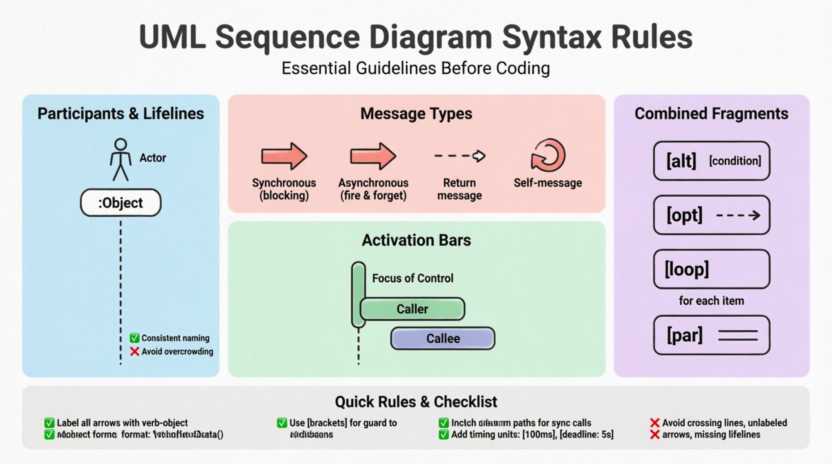
1. Defining Participants and Lifelines 🏗️
The foundation of any sequence diagram is the participant. These entities represent the objects, actors, or subsystems involved in the interaction. Proper definition of participants establishes the boundaries of the system and clarifies who is responsible for specific actions.
Lifeline Representation
- Vertical Dashed Lines: Every participant must have a lifeline represented by a vertical dashed line extending downwards from the participant instance.
- Top Alignment: The participant instance box (a rectangle) sits at the top of the lifeline.
- Consistency: Ensure the same participant is not represented by multiple lifelines unless modeling concurrent threads or distinct instances of the same class.
Participant Types
- Actor: Represented by a stick figure icon. Use this for human users or external systems initiating the process.
- Object/Class: Represented by a rectangle. Use a colon prefix for object instances (e.g.,
:CustomerService) to indicate an instance of a class. - Boundary/Control: In MVC architectures, distinguish between boundary objects (UI) and control objects (Logic).
Common Mistakes to Avoid
- Missing Lifelines: Do not draw messages that connect to empty space. Every message must terminate on a valid lifeline.
- Inconsistent Naming: Use full class names or clear abbreviations throughout the diagram. Do not mix
:Userand:Customerfor the same entity. - Overcrowding: If too many participants exist, consider splitting the diagram into multiple sequences or using a general sequence diagram for overview.
2. Message Notation and Flow 📩
Messages represent the communication between participants. The syntax of the arrow dictates the nature of the call, the return type, and the timing. Correct arrow notation is vital for developers to understand whether a process blocks or runs in the background.
Arrow Types
- Synchronous Call: A solid line with a filled arrowhead. The sender waits for a response before continuing execution.
- Asynchronous Call: A solid line with an open arrowhead. The sender does not wait for the response.
- Return Message: A dashed line with an open arrowhead. This indicates data or control returning to the caller.
- Self-Message: A message sent from an object to itself. Represented by a loop arrow starting and ending on the same lifeline.
Table: Message Syntax Comparison
| Message Type | Arrow Style | Behavior Description |
|---|---|---|
| Synchronous | Filled Arrowhead | Blocking call; waits for completion |
| Asynchronous | Open Arrowhead | Non-blocking; fire and forget |
| Return | Dashed Line + Open Arrow | Response to a previous call |
| Signal | Open Arrowhead + No Line | Event-based communication |
Labeling Conventions
- Verb-Object Format: Use verbs to describe actions (e.g.,
fetchData(),submitOrder()). - Parameters: Include parameters in parentheses if they are critical to the logic (e.g.,
login(username, password)). - Sequence Numbers: Assign a sequence number to each message (e.g., 1, 2, 3) to clarify the chronological order, especially in complex flows.
3. Activation Bars and Focus of Control 🔄
Activation bars (also known as focus of control) indicate the period during which an object is actively performing an action. They appear as thin rectangles on the lifeline where the object is processing.
When to Use Activation Bars
- Processing Time: Show when a participant is busy. This helps identify bottlenecks in the system.
- Nested Calls: When a message triggers a call to another object, the activation bar on the caller overlaps with the activation bar of the callee.
- Long-Running Tasks: Use activation bars to denote tasks that take significant time, distinguishing them from instant checks.
Syntax Rules for Activation
- Alignment: The top of the activation bar aligns with the start of the incoming message. The bottom aligns with the outgoing return message.
- Overlap: Overlapping activation bars on different lifelines visually demonstrate concurrent processing or dependency.
- Clarity: Avoid drawing activation bars for trivial, instantaneous operations unless they are critical to the flow explanation.
4. Combined Fragments for Logic Control 🧩
Complex systems rarely follow a single linear path. Combined fragments allow you to model conditional logic, loops, and parallel processing within the sequence diagram. These fragments are enclosed in a box with a label in the top-left corner.
Standard Fragments
- alt (Alternative): Represents if-else logic. Only one fragment executes based on the condition.
- opt (Option): Represents optional behavior. The fragment executes only if the condition is true.
- loop: Represents a loop structure (for, while). Place a repetition condition in the top left (e.g.,
for each item). - break: Represents an exit condition within a loop or alt block.
- par (Parallel): Represents concurrent execution. Messages in this block happen simultaneously.
Guard Conditions
- Bracket Notation: Guard conditions must be enclosed in square brackets (e.g.,
[user is admin]). - Placement: Place the guard condition at the top of the fragment box or directly on the message arrow for simple conditions.
- Boolean Logic: Use clear boolean expressions. Avoid vague terms like
if valid; specify[status == valid].
5. Timing and Constraints ⏱️
Sequence diagrams are not just about logical flow; they often convey timing requirements. While UML primarily focuses on logical interaction, adding timing constraints adds precision to the design.
Time Constraints
- Duration: Specify how long a message takes (e.g.,
[100ms]). - Deadline: Indicate when a response must be received (e.g.,
[deadline: 5s]). - Time Unit: Always specify the unit of time (ms, s, min) to avoid ambiguity.
Object Lifetimes
- Creation: Use a
createmessage to show when an object is instantiated. - Termination: Use an
destroysymbol (an X) at the bottom of a lifeline to show object disposal.
6. Common Syntax Violations to Avoid ❌
Even experienced designers make mistakes. Identifying common violations helps maintain high-quality diagrams that are easy to read and implement.
Structural Violations
- Crossing Lines: Minimize message lines crossing each other. Use
altorparfragments to reorder messages if necessary. - Unlabeled Arrows: Never draw an arrow without a label. It implies an undefined action.
- Broken Lifelines: Ensure lifelines are continuous. Do not break them for visual spacing unless indicating a significant time gap (use dashed lines).
Logical Violations
- Missing Returns: If a synchronous call is made, a return message should be depicted unless the context implies otherwise.
- Unreachable Paths: Ensure that every path within an
altblock leads to a logical conclusion or return. - Conflicting Messages: Do not show two different messages sent to the same object at the exact same vertical position unless they are part of a
parblock.
7. Aligning Diagrams with Implementation 🛠️
The ultimate goal of a sequence diagram is to guide the coding process. Therefore, the syntax must reflect the reality of the codebase.
Consistency Checks
- Naming Alignment: Method names in the diagram should match the method signatures in the codebase.
- Parameter Types: Ensure the types of parameters mentioned in the diagram match the expected types in the implementation.
- Error Handling: Include error paths in the diagram. If an API returns a 404, the diagram should show the exception handling flow.
Version Control
- Diagram Updates: Treat diagrams as code. Update them when the logic changes. A diagram that does not match the current code is technically debt.
- Documentation Link: Store diagrams in the same repository as the source code to ensure they are versioned together.
8. Best Practices for Readability 📖
Readability is the primary metric for a successful diagram. If a developer cannot understand the flow in five minutes, the diagram has failed.
- Top-Down Flow: Arrange messages chronologically from top to bottom. Left-to-right can be used for parallel processes.
- Color Coding: While syntax rules dictate black and white, using color to distinguish between different types of messages (e.g., red for errors, green for success) can aid quick scanning.
- White Space: Use spacing to group related interactions. Avoid cramming the diagram.
- Legend: If using custom notations or non-standard arrows, provide a legend at the bottom of the page.
9. Impact on System Architecture 🏛️
Adhering to strict syntax rules has a downstream effect on the overall architecture. It forces the designer to think about interfaces and contracts before writing code.
Interface Definition
- Contract Clarity: Clear message syntax defines the contract between services. It specifies exactly what is required and what is provided.
- Decoupling: By defining interactions clearly, you can decouple modules. If the diagram shows a dependency, you know where to decouple it.
Maintainability
- Onboarding: New team members can understand the system flow faster if the diagrams follow standard syntax.
- Refactoring: When refactoring code, the sequence diagram serves as a regression test. It shows what the behavior should look like.
10. Review Checklist ✅
Before finalizing your UML sequence diagram, run through this checklist to ensure compliance with syntax rules.
- Participants: Are all lifelines labeled clearly? Are actors distinguished from objects?
- Messages: Are arrows correctly labeled with verb-object notation? Are arrowheads correct for sync/async?
- Activation: Do activation bars match the message start and end points?
- Fragments: Are
alt,loop, andparblocks properly labeled with conditions? - Completeness: Is there a return path for every synchronous call?
- Consistency: Do the names match the codebase documentation?
By rigorously following these syntax rules, you create a design artifact that serves as a reliable contract between design and implementation. This reduces ambiguity, speeds up development, and ensures the final product meets the architectural intent. The effort invested in standardizing your diagrams pays off in reduced debugging time and clearer team communication.