


UML State Machine Diagrams, also known as State Diagrams or Statecharts, are powerful behavioral diagrams in the Unified Modeling Language (UML) that model the dynamic behavior of a system, object, or process. They illustrate the various states an entity can be in during its lifetime and the transitions between those states triggered by events, conditions, or actions. These diagrams are particularly useful for event-driven systems where behavior depends on historical context, such as user interfaces, device controllers, protocols, and business workflows.
Unlike sequence or activity diagrams that focus on interactions or flows, state machine diagrams emphasize how an object responds to stimuli over time, making them ideal for modeling lifecycles and reactive systems.
Key Concepts in UML State Machine Diagrams
Understanding the core elements is essential for creating accurate and effective diagrams:
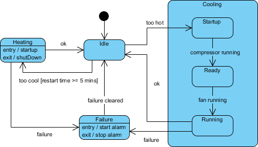
- State: A condition or situation in which an object satisfies certain criteria, performs an activity, or waits for an event. Represented as a rounded rectangle. States can include entry/exit actions (e.g., entry / startTimer) and internal activities.
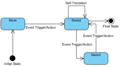
- Initial State: The starting point, shown as a solid black circle.
- Final State (End State): Indicates termination of the state machine, depicted as a circle surrounding a smaller solid circle.
- Transition: A directed arrow from one state to another, labeled with the triggering event, guard condition (in square brackets, e.g., [balance > 0]), and optional effect (e.g., / withdrawFunds).
- Composite State (Submachine State): A state containing nested substates, allowing hierarchical decomposition for complex behaviors.
- Orthogonal Regions: Divided by dashed lines within a composite state, representing concurrent (parallel) substates.
- History States:
- Shallow History: Remembers the most recent substate in the immediate composite state.
- Deep History: Remembers substates at all nesting levels.
- Pseudostates:
- Fork: Splits a transition into concurrent flows.
- Join: Merges concurrent flows back into one.
- Choice: Dynamic branching based on guards.
- Junction: Static merging or branching.
These elements ensure diagrams adhere to correct UML notation, capturing guards, triggers, entry/exit actions, and more.
Examples of UML State Machine Diagrams
State machine diagrams shine in real-world scenarios:
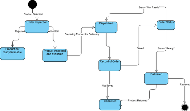
- Order Processing in an E-Commerce System An order object might transition through states like “New”, “Payment Pending”, “Processing”, “Shipped”, “Delivered”, or “Cancelled”. Events such as “pay()”, “confirmShipment()”, or “cancel()” trigger changes, with guards like “[paymentSuccessful]”.
Explanation of the UML State Machine Diagram
This UML State Machine Diagram models the behavior of a simple vending machine during a single transaction. It shows the different states the vending machine can be in and how it moves (transitions) between those states in response to user actions or events.
Main Flow for a Successful Purchase
- The machine begins in the Idle state (starting point indicated by a black circle).
- When the user inserts a coin, the machine transitions to InsertCoin (handling payment insertion).
- After successful payment processing, it moves to WaitingForSelection, where the user can start selecting an item.
- Inside a grouped section called Waiting for Selection (a composite state that organizes related sub-behaviors):
- The user chooses an item, moving to SelectItem.
- From here:
- If the user confirms the selection, the machine goes to Dispense.
- If the user cancels, it goes to Refund.
- In Dispense, the item is released, transitioning to Shipped (indicating successful delivery).
- Finally, it reaches the end state (a circled black dot), completing the transaction.
Cancellation and Refund Path
- From SelectItem, if the user cancels, the machine enters Refund.
- It then returns money and goes back to Idle, ready for the next customer.
Error Handling Path
- During InsertCoin, if an invalid coin is detected, the machine transitions directly to Error.
- From Error, it goes straight to the end state (transaction aborted, possibly without refund).
Key Features Highlighted
- Composite State: The “Waiting for Selection” box groups the selection-related states (WaitingForSelection, SelectItem) to keep the diagram organized and reduce clutter.
- Transitions: Arrows are labeled with events like “insert_coin()”, “choose_item()”, “confirm_selection()”, “cancel_selection()”, “dispense_item()”, “return_money()”, and “invalid_coin()”. These represent triggers that cause state changes.
- No guards (conditions) or actions (effects) are shown in this simplified version, focusing purely on states and event-triggered transitions.

This diagram ensures the vending machine’s behavior is predictable: it only allows certain actions in specific states (e.g., you can’t dispense without selecting, or refund without canceling).
Boosting Productivity with Visual Paradigm’s AI-Assisted State Machine Diagram Generator
Traditional diagramming tools require manual placement of states, transitions, and labels, which can be time-consuming for complex behaviors. Visual Paradigm revolutionizes this with its AI-powered State Machine Diagram Generator, integrated into an intuitive AI chatbot interface.
Key benefits include:
- Instant Creation from Natural Language: Describe the object’s behavior in plain English (e.g., “Create a state machine diagram for an Automated Toll Collection System”), and the AI instantly generates a clean, accurate UML-compliant diagram.
- Conversational Refinement: Iterate effortlessly—say “Add a guard for low balance” or “Insert a new state for error handling”—and watch the diagram update in real-time. This uncovers edge cases and validates logic without manual redrawing.
- Productivity Gains:
- Converts descriptions into precise states, transitions, events, guards, and actions.
- Automatically arranges layouts for readability, even in complex diagrams.
- Enables rapid prototyping and exploration of behavioral patterns.
- Analyzes for issues like invalid or unreachable transitions.
- Serves as up-to-date documentation, bridging design to implementation (e.g., code generation).
Whether modeling UI components, device lifecycles, or business processes like 3D printing workflows or voting platforms, this tool shifts focus from tedious drawing to creative problem-solving.
Ready to revolutionize your workflow? Visual Paradigm’s AI-assisted generator makes state-driven design faster, more accurate, and collaborative—empowering teams to build reliable, state-aware systems with confidence.
Resource
- State Diagram Quick Tutorial: Master UML State Machines in Minutes: A beginner-friendly guide to creating and understanding state diagrams using Visual Paradigm, covering core concepts and practical modeling techniques.
- What is a State Machine Diagram? A Comprehensive Guide to UML State Diagrams: An in-depth explanation of state machine diagrams in UML, including their purpose, components, and real-world applications in system design.
- Generating Source Code from State Machines in Visual Paradigm: Detailed instructions on generating code from state machine diagrams in Visual Paradigm, enabling developers to implement complex state-driven logic efficiently.
- Free State Machine Diagram Templates for Visual Paradigm: Download and use professionally designed state machine diagram templates to model system behavior and state transitions efficiently.
- Visual Paradigm: State Machine Diagram User Guide: Comprehensive guide on creating and using state machine diagrams in Visual Paradigm to model complex system behaviors and state transitions.
- Understanding State Diagrams in UML: An introductory overview of state diagrams in UML, explaining their purpose, components, and applications in system modeling.
- Step-by-Step State Machine Diagram Tutorial: Interactive tutorial guiding users through creating state machine diagrams with Visual Paradigm, from basic concepts to advanced modeling.
- State Machine Diagram Software Features – Visual Paradigm: Explore the powerful features of Visual Paradigm’s state machine diagram tool for modeling complex state transitions and system behavior.
- State Machine Diagram Software Features – Visual Paradigm: Explore the powerful features of Visual Paradigm’s state machine diagram tool for modeling complex state transitions and system behavior.
- How to Create a State Machine Diagram in Visual Paradigm: Detailed step-by-step instructions for creating state machine diagrams using Visual Paradigm’s intuitive interface and modeling tools.
- Vision and Strategy Template – Pre-Designed Framework for Strategic Planning: Use ready-made templates to quickly develop vision statements, mission goals, and strategic initiatives with Visual Paradigm.
- Visual Paradigm – UML State Machine Diagram Tool: A comprehensive online UML tool that supports creating, editing, and exporting detailed state machine diagrams.